I used to solder all my SMD components by hand. I then upgraded to a reflow oven and started applying solder paste to my boards with a solder paste syringe. It's cumbersome, and tricky squeezing out just the right amount of solder. Fine-pitched ICs usually need some kind of clean up work on the pins with a copper braid.
I've always wanted to try out using a solder stencil. I never bothered ordering one for any of my past projects because it always seemed like a waste of money. It's a lot of money to spend on something that'll be used for five minutes, and then thrown in the garbage. It would be worth it if it was going to be used many times, but all the projects I work on are one-offs.
I really wanted to try one for this project. I know I could have soldered it by hand. I've soldered all these components before, but that 28-pin MAX6921 is a real pain to solder.
I uploaded by board file to OSH Stencils. I would have loved a stainless steel stencil, but it would have cost $27.49. I can't justify spending almost $30 bucks on something that will be used once. The 5mil Polyimide stencil was $13.74. That's still a lot of money for a little piece of plastic that's most likely going to go in the garbage after it's been used. Not to mention, another $3 for shipping. I really want to try my hand at using a stencil, and this is a pretty complicated board, so I figured I'd go for it.
A few days later, I had my stencil in hand. It's really thin. I had to hold it down with some magnets for the photo. It wouldn't stop curling up.
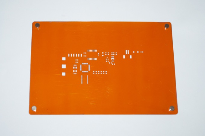
It comes with a test print of your board so you can see that everything lines up OK.
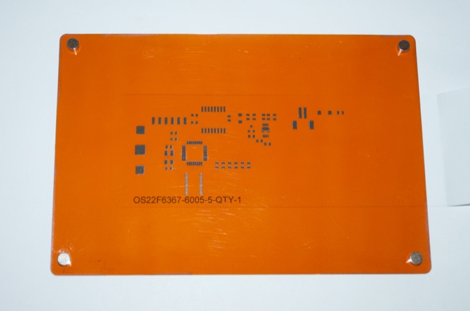
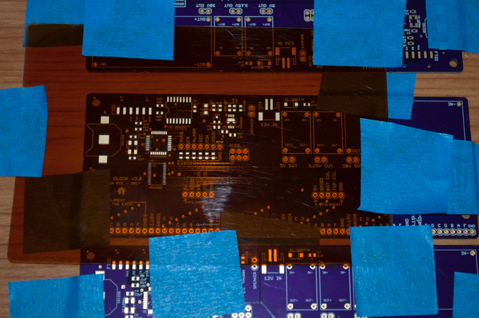
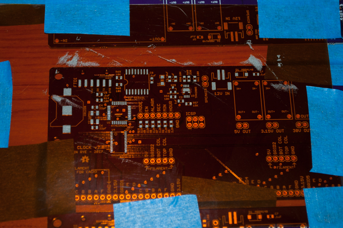
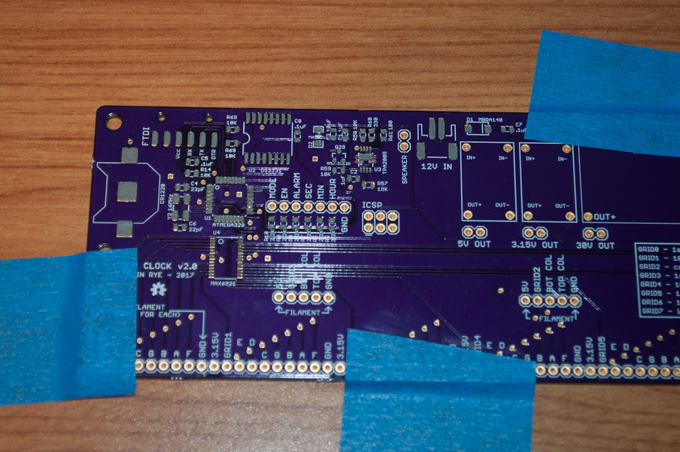
My boards arrived in the mail a few days later. They look awesome.
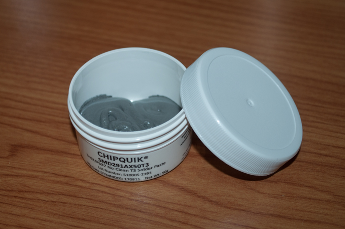
The solder paste that I ordered also arrived. Will you look at that. $13 bucks for a jar of solder paste and it's not even half full. I would have felt better if they used a smaller jar and filled it to the top.
I didn't want to tape the stencil to the table fearing that it would bow in the center. I taped it to some PCBs that were taped to the table. That way the whole thing is completely flat against the surface of the PCB.
I used the included solder paste spreader and scrapped a blog of it over the top of the stencil. It was so easy to apply. It just magically fills in all the holes and goes exactly where it needs to be.
I then carefully removed the stencil. It looks great. There is some solder paste between the pins on the ATmega328 and the MAX6921, but it's such a thin layer of paste, that it'll go where it needs to go once it liquifies in the oven.
I then placed all my components on the pads.
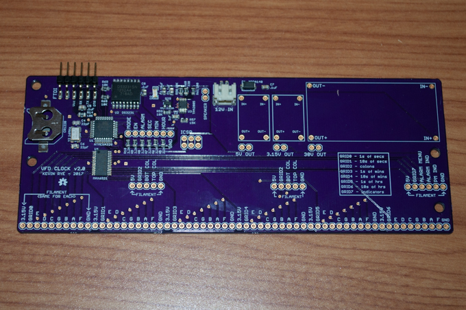
After a quick reflow, the SMD part of the board was complete. I can't believe how much easier and quicker it was to do with the aid of a stencil. From start to finish, I think I put this board together in under 15 minutes.
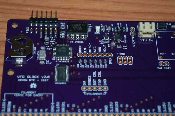
Before proceeding any further with the assembly, and potentially wasting components, I burned the bootloader and uploaded a sketch in order to verify that the logic was working.
Success!
Here it is in action:
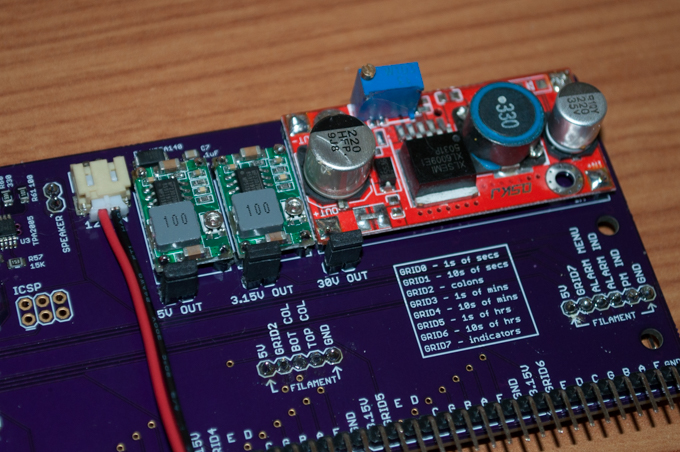
I then installed the voltage regulators and header pins.
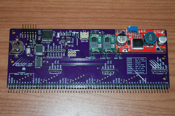
I added 3 jumpers to the board for the regulators so that I could disconnect the outputs. That way I could adjust them in-circuit. By default, the DC-DC regulators output the full input voltage. That means if I connect my 12V supply, I'll let the smoke out of my logic.
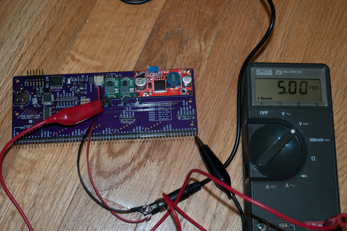
I connected my 12V supply and dialed in the 5V and 3.15V regulators.
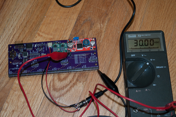
I then dialed in the output of the boost converter to 30 volts.
Finally, I connected the jumpers in order to supply the voltage to the board.
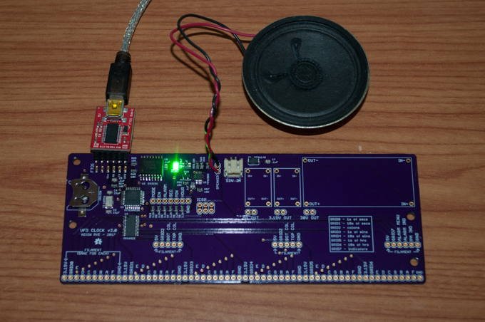
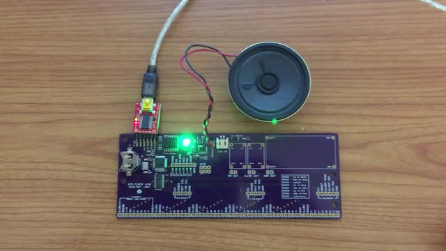
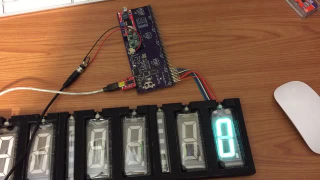
I then uploaded a test sketch to count from 0 to 9. It looks like the rest of the logic is good.
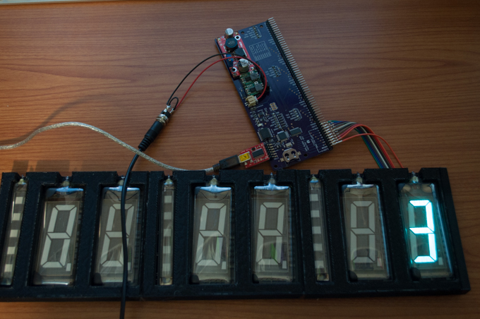
Here it is in action:
All the logic works perfectly without the need to go back and do any touch ups on the board. The fact that I didn't have to spend any time cleaning up the board, and that I had it assembled in no time, the $16 bucks that I dropped on the stencil was money well spent. I probably won't spend that kind of money on every board, but for the bigger, more complicated boards like this, it's definitely worth the money.
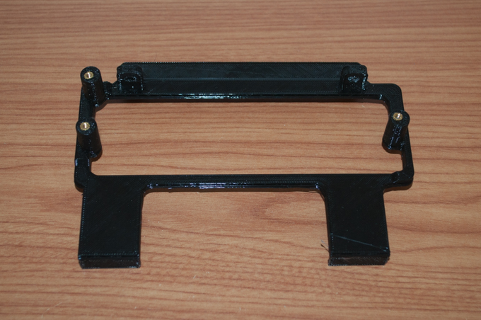
With the PCB assembled and verified working, it was time to 3D-print something to mount it. I threw something together in SketchUp, printed it, and installed some 4-40 threaded inserts.
Despite ordering the mainboard and button board PCBs at the same time, they ended up on two different panels at OSH Park. The boards shipped two days apart. However, they both landed at my local distribution center on Saturday morning so I thought I was going to get them both for the weekend. While the mainboard PCB was delivered, the button board missed the Saturday mail. Unfortunate.
Fast forward two days, and I had my new button boards.
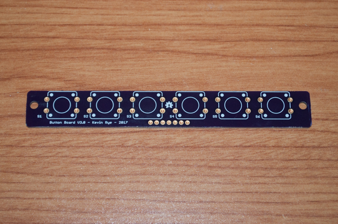
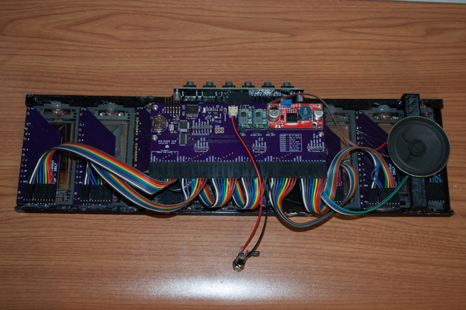
I soldered the buttons on and connected them to the mainbaord.
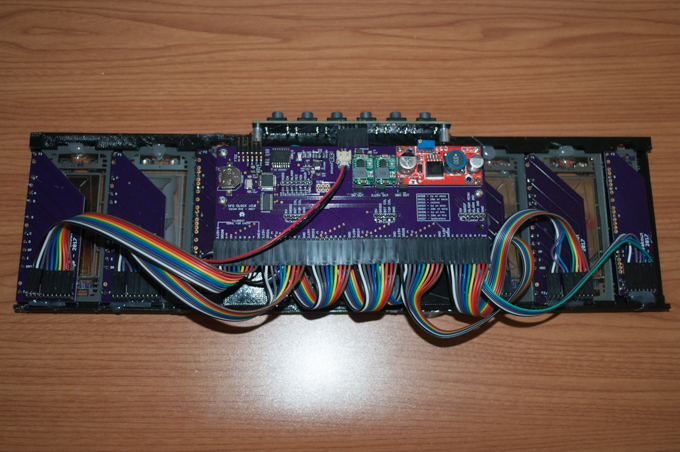
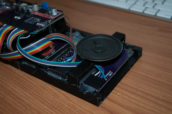
I put together all my custom ribbon cable assemblies and made all the necessary connections. I then hot-glued the PCB mount to the display rig. I have to admit, those wires looked a lot better "on paper". Those cables take up a lot more space that I anticipated. I was hoping that the clock was going to be about an inch thick, but I don't know if I'll be able to pull that off with so many cables all bunched up like that.
The last thing to do was to design a mount for the speaker.
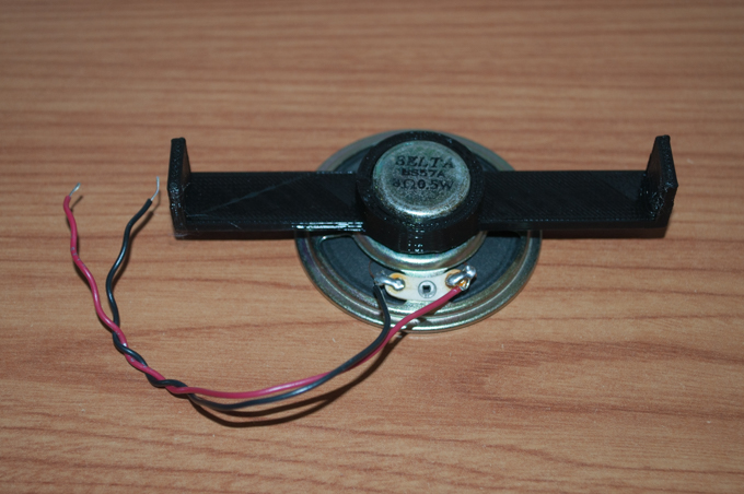
I then hot-glued the speaker mount to the display rig.
That should do it. The clock internals are complete.
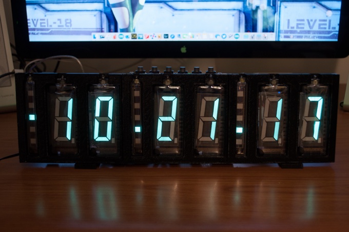
The moment of truth. I applied power and verified that everything was good to go. The time, date, and alarm are now set.
Time Mode - The PM light works as it should as well as the light under it that indicates the alarm is enabled.
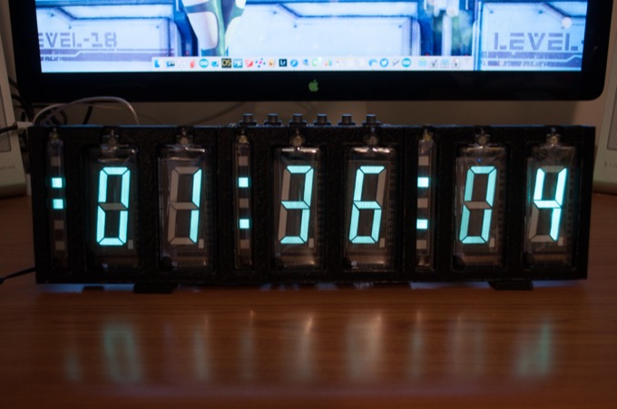
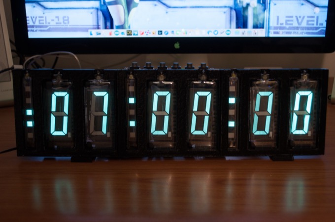
Date Mode - Colons turn into decimals, PM light is disabled, alarm enabled light is on.
Alarm Mode - PM light is on, in alarm mode light is on, alarm is enabled light is on.
All I have to do now is design a case for it. Although, in order to do it right, I think I'll have to wait until my Glowforge ships. I'm tired of paying three times the price to get things cut and shipped from Ponoko. The case will cost well over $100 to get it from Ponoko. I think it's worth it to wait a few more months until I have my own Glowforge and a ton of free Proofgrade materials to play with.
See this project from start to finish:
More VFDs!!! VFD Breakouts Large VFD Clock - Part I VFD AC Filament Driver Large VFD Clock - Part II VFD AC Filament Driver V1.1 Large VFD Clock - Part III Large VFD Clock - Part IV
Large VFD Clock - Part V