AppleToTheCore
Check out my vintage Apple collection.
RescueMyClassicMac
Do you need old system software disks to boot your vintage Mac?
Check out my vintage Apple collection.
Do you need old system software disks to boot your vintage Mac?
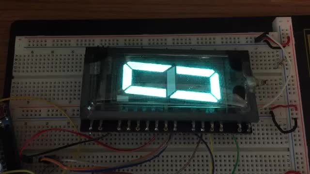
int a[20] = {1, //GRID
             0,
             0,
             0,
             0,
             0,
             1, //A
             0, //B
             0, //C
             0, //D
             0, //E
             0, //F
             0, //G
             0,
             0,
             0,
             0,
             0,
             0,
             0
            };
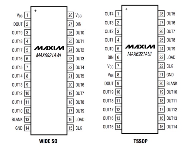
int clk = 3;
int load = 5;
int din = 4;

int a[20] = {1,0,0,0,0,0,1,0,0,0,0,0,0,0,0,0,0,0,0,0};

int k = 0;

void setup() {
  pinMode(din, OUTPUT);
  pinMode(load, OUTPUT);
  pinMode(clk, OUTPUT);
  digitalWrite(clk, LOW);
  digitalWrite(load, LOW);
  digitalWrite(din, LOW);
}

void loop() {
  for (int i = 0; i < 20; i++) {
    if (i == k) digitalWrite(din, 1);
    else  digitalWrite(din, 0);
    digitalWrite(clk, HIGH);
    delay(10);
    digitalWrite(clk, LOW);
    delay(10);
  }
  digitalWrite(clk, LOW);

  for (int i = 19; i >= 0; i--) {
    digitalWrite(din, a[i]);
    digitalWrite(clk, HIGH);
    delay(10);
    digitalWrite(clk, LOW);
    delay(10);
  }

  digitalWrite(load, HIGH);
  delay(10);
  digitalWrite(load, LOW);

  delay(200);

  k = k + 1;
  if (k > 19) k = 0;
}
int a[20] = {1,0,0,0,0,0,1,0,0,0,0,0,0,0,0,0,0,0,0,0};
int b[20] = {1,0,0,0,0,0,0,1,0,0,0,0,0,0,0,0,0,0,0,0};
int c[20] = {1,0,0,0,0,0,0,0,1,0,0,0,0,0,0,0,0,0,0,0};
int d[20] = {1,0,0,0,0,0,0,0,0,1,0,0,0,0,0,0,0,0,0,0};
int e[20] = {1,0,0,0,0,0,0,0,0,0,1,0,0,0,0,0,0,0,0,0};
int f[20] = {1,0,0,0,0,0,0,0,0,0,0,1,0,0,0,0,0,0,0,0};
int g[20] = {1,0,0,0,0,0,0,0,0,0,0,0,1,0,0,0,0,0,0,0};
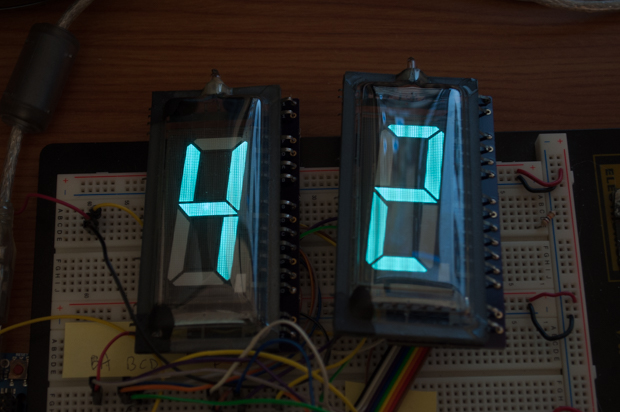
int a[20] = {1, //GRID
             0,
             0,
             0,
             0,
             0,
             1, //A
             1, //B
             1, //C
             1, //D
             0, //E
             0, //F
             1, //G
             0,
             0,
             0,
             0,
             0,
             0,
             0
            };
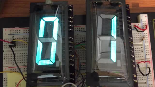
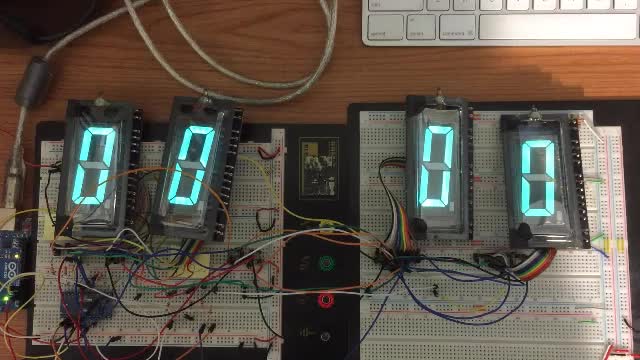
byte zero[20] = {1,0,0,0,0,0,1,1,1,1,1,1,0,0,0,0,0,0,0,0};
byte one[20] = {1,0,0,0,0,0,0,1,1,0,0,0,0,0,0,0,0,0,0,0};
byte two[20] = {1,0,0,0,0,0,1,1,0,1,1,0,1,0,0,0,0,0,0,0};
byte three[20] = {1,0,0,0,0,0,1,1,1,1,0,0,1,0,0,0,0,0,0,0};
byte four[20] = {1,0,0,0,0,0,0,1,1,0,0,1,1,0,0,0,0,0,0,0};
byte five[20] = {1,0,0,0,0,0,1,0,1,1,0,1,1,0,0,0,0,0,0,0};
byte six[20] = {1,0,0,0,0,0,1,0,1,1,1,1,1,0,0,0,0,0,0,0};
byte seven[20] = {1,0,0,0,0,0,1,1,1,0,0,0,0,0,0,0,0,0,0,0};
byte eight[20] = {1,0,0,0,0,0,1,1,1,1,1,1,1,0,0,0,0,0,0,0};
byte nine[20] = {1,0,0,0,0,0,1,1,1,1,0,1,1,0,0,0,0,0,0,0};