I last left off with the successful assembly of an
NE-2 nixie colon. That was the last piece of the puzzle I needed to figure out before sending my PCBs off to be fabbed. I didn't want to order the boards and then find out I couldn't pull off my DIY colon idea.
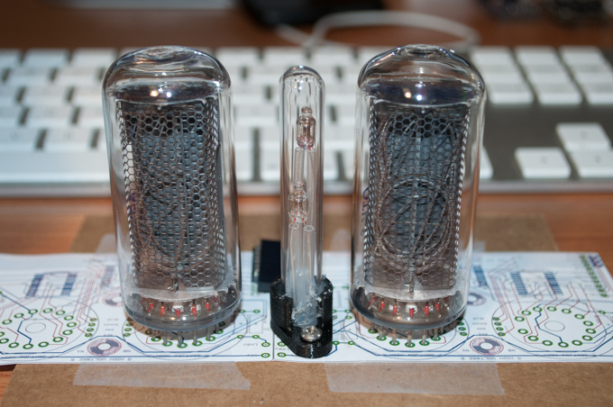
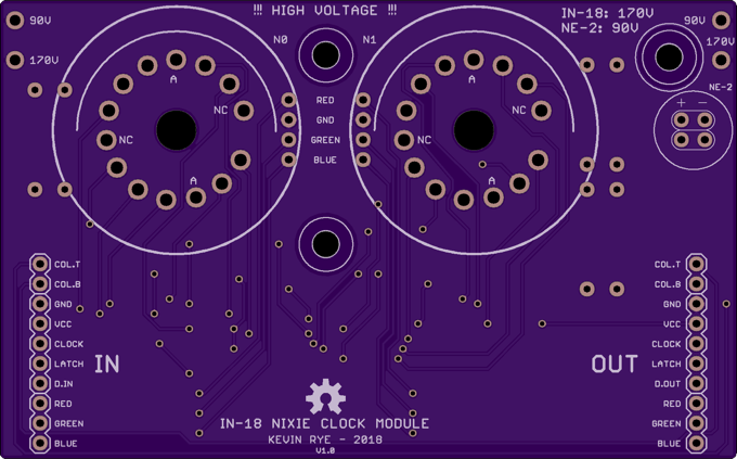
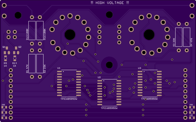
I put the finishing touches on the board and printed out a few copies. The colon should sit at equal distances from both tubes. Everything in EAGLE checks out, but I wanted to place the tubes on the printout just as a sanity check. I also wanted to make sure that the headers I'm using to connect one board to the other are properly spaced.
Everything looks good.
I then ordered my boards from OSH Park.
Luckily, I got a free upgrade to their Super Swift service. The order was placed Monday, I had them on Saturday!
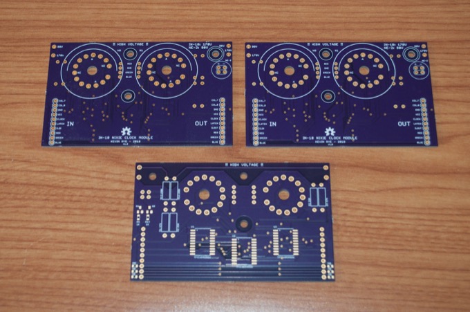
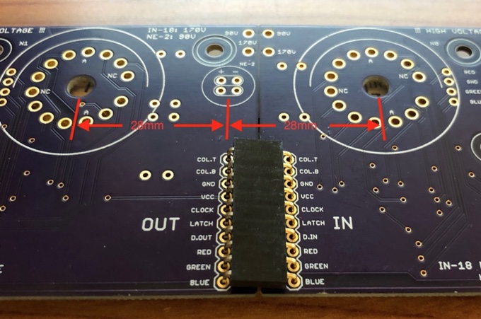
I put two PCBs side-by-side and made sure one last time that the connector spacing was good. It's perfect. The colons are exactly 28mm from each nixie.
These boards came so fast that I didn't have time to order a stencil. I wasn't going to bother, but after a day or two I figured that I probably should just to make my life easier. Once I found out that the boards would be here in 5 days, I didn't bother ordering the stencil. There's no way I could have these boards arrive on the weekend and not put one together just because the stencil was still in the mail.
With that, I applied my solder paste with a syringe. Not my best work, but it should go where it needs to once it's in the oven.
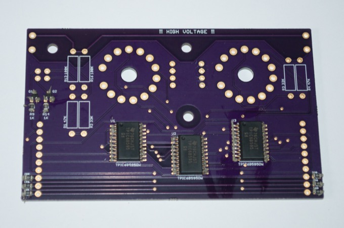
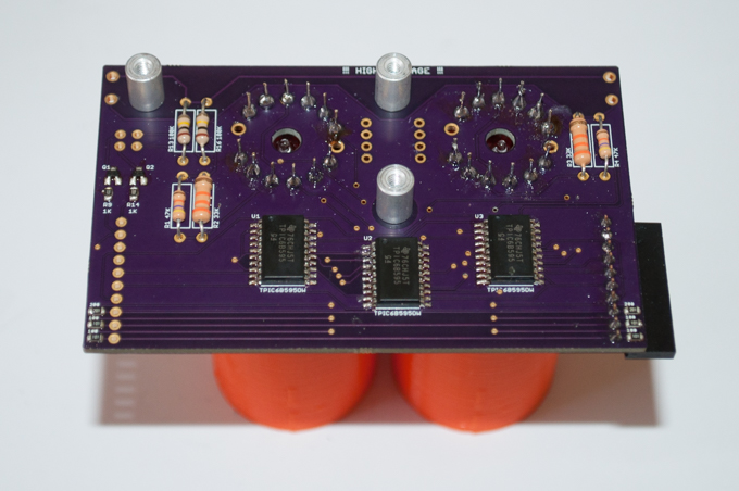
That came out really nice. I only had to touch up one leg on one of the chips. Everything else is perfect.
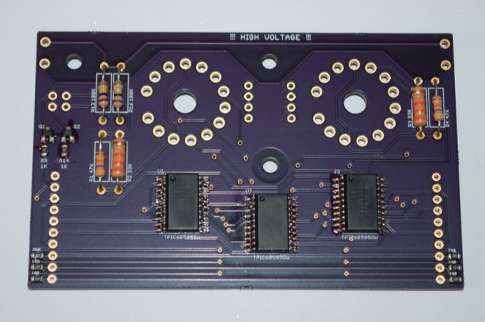
I then soldered in the resistors. It's too bad that I only had 1/2 watt 33K resistors. I like all my resistors to match in size. Call me OCD.
I then soldered in the first tube.
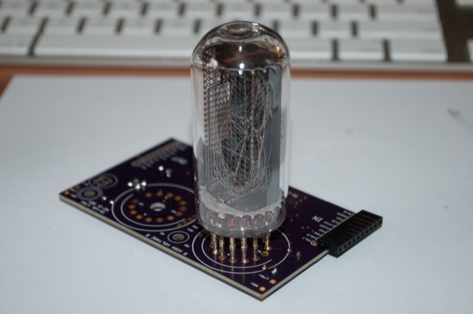
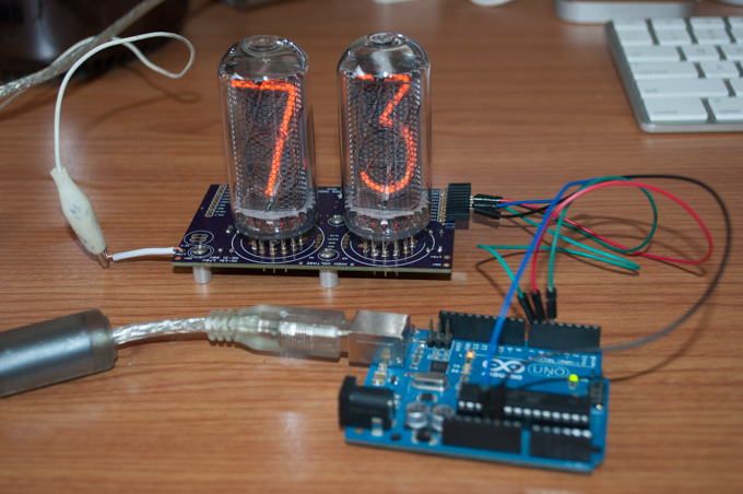
I then uploaded some code to make sure that what I had so far worked.
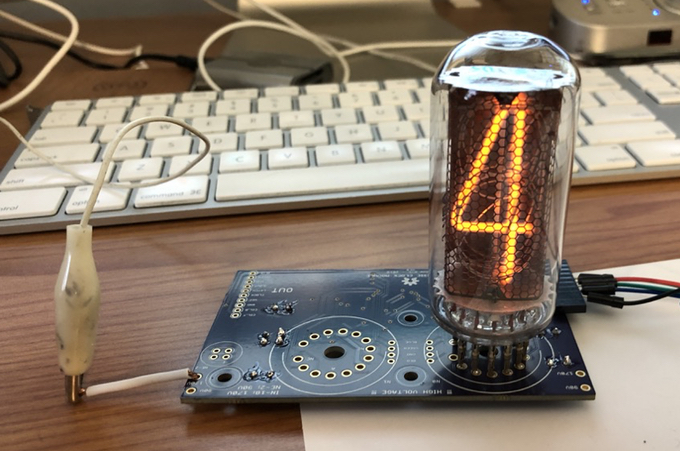
Good to go! Looks like it works!
Time to solder in the second tube.
It was at this point that I realized how difficult it was going to be to keep the second tube nice and straight and aligned with the first while soldering it. I pretty much eye-balled the first tube, but that's not going to fly with the second tube. Once all six tubes are in, I don't want them all crooked and mounted all willy-nilly.
I jumped into SketchUp and designed a jig to hold the tubes straight. It has some screw holes at the bottom so that I can mount it to the board.
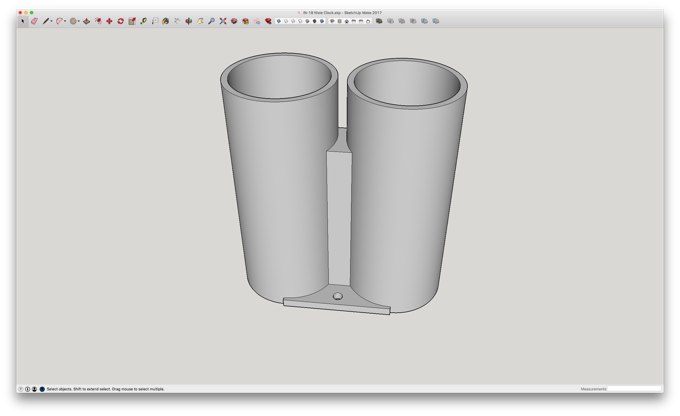
I printed it on low quality just to speed up the print. It doesn't need to be anything fancy, it just needs to work.
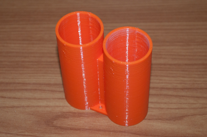
A perfect fit.
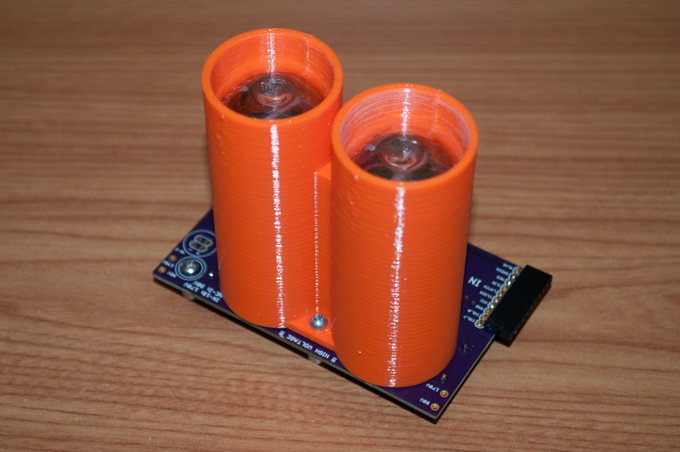
I made it a little taller than the tubes so that I can flip it over and use it to steady the assembly while soldering the tubes.
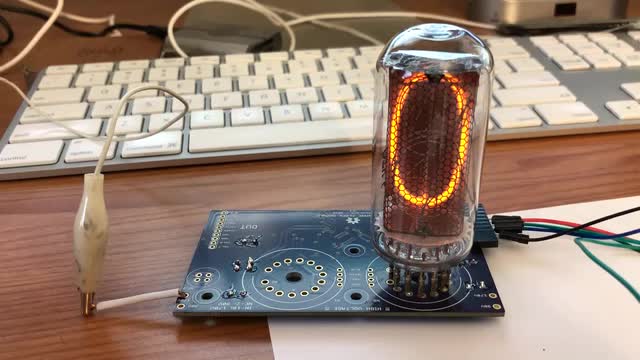
One more test to make sure that it works. Nice!
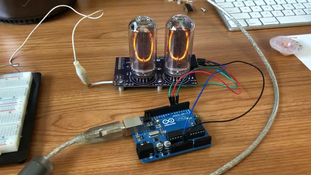
Here it is in action:
Next up are the RGB LEDs. I didn't put LEDs in my first
IN-12 clock since I ran out of I/O pins. I used the same mainboard on my
IN-14 clock but I was able to get around not having enough I/O to run the LEDs by just hard-wiring the blue anode of the LEDs. I didn't want my IN-18 clock to just be a larger version of my IN-14 clock, so I made sure to include RGB LEDs as a new feature.
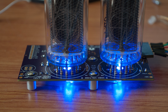
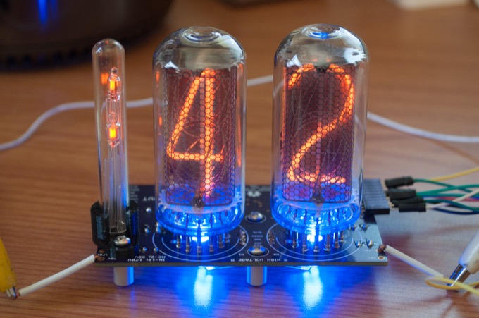
The plan was to push the LEDs through the holes underneath the nixies, but I didn't realize how close the glass stem seals on the nixies came to the PCB. The LEDs don't go in the holes, but I think they are close enough that I think that they should still shine up through the nixies well enough.

Yup, that looks pretty good. Plus, it's pretty bright in here today so I think it'll be fine.
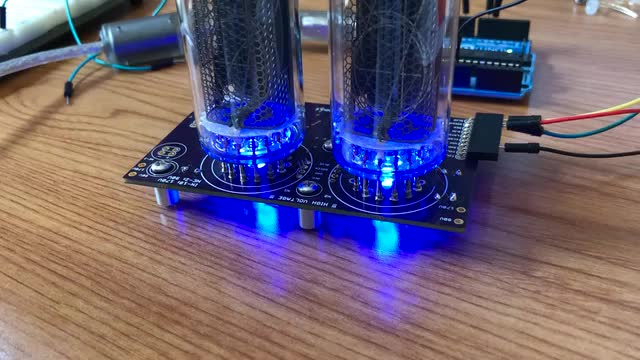
I uploaded some code to cycle through the RGB colors to make sure that they worked OK. The RGB leads are connected to PWM channels on the Arduino, so I can fade them in and out too. That means I can have the LEDs fade through the whole rainbow. I’m not sure what I’m going to do with them yet. I might have it just fade slowly throughout the day. Or have it change a different color on the hour. I might also put a knob on it so I can just dial in the color I want. We'll see.
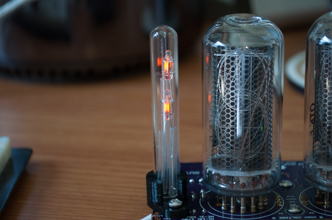
So far so good. The last thing to do is install the colon.
I mounted the 3D-printed base to the PCB and slid the leads through and soldered them in place.
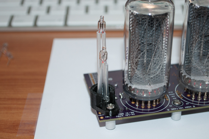
I then slid the glass tube into position. Since both NE-2s are connected to transistors, I can control them independently. That's also a new feature.
I then modified my code to include the colons flashing, the numbers counting, and the RGB LEDs cycling. Everything works!
Here it is action:
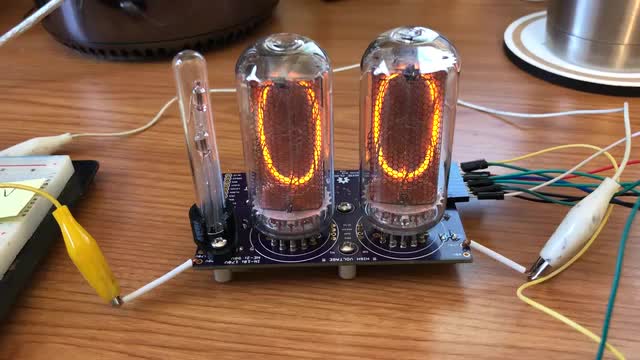
OK! One down, two to go!
See this project from start to finish:
IN-18 Nixies TPIC6B595 Shift Registers IN-18 Nixie Clock - Part I NE-2 Neon Bulbs IN-18 Nixie Clock - Part II
IN-18 Nixie Clock - Part III IN-18 Nixie Clock - Part IV IN-18 Nixie Clock - Part V