With the prototype working, and the code 99% complete, it was time to put together a PCB and get to work on an enclosure. I really want this clock to look sweet.
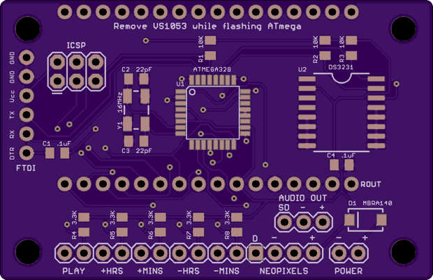
I put together a PCB and sent it off to OSH Park.
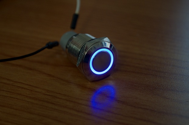
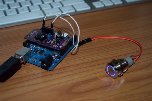
A few days later, while looking online for some parts, I rediscovered this illuminated metal push button. I remembered seeing them on
Adafruit’s site a few years ago and was tempted to pick up one for the hell of it. It’ll come in handy one day, I thought. It’s a sweet looking button. However, at $5 bucks a pop, I held off on ordering one until I really needed it for a specific project. Well, that day has come. Once I saw it again, I just had to have one.
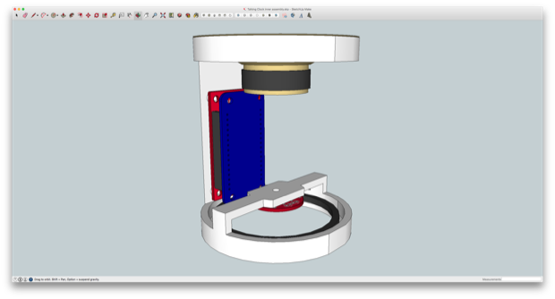
The enclosure will consist of two parts: the main housing, and an inner chassis. The inner chassis will hold the electronics. I can then slide the chassis into the main housing, which will basically be somewhat of an outer shell.
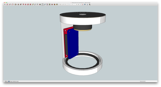
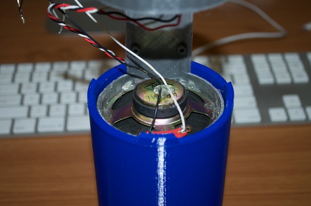
I first started out by printing the inner chassis so that I could check that all my dimensions were OK. I want to make the outer casing tight enough so that the inner chassis will slide in and be held secure by friction and not require any additional mounting hardware.
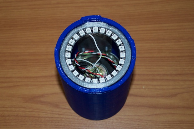
I do admit, the print came out a little rough, but I’m off to a good start. It might need a few tweaks for aesthetics, but everything fits perfectly. The speaker and the Neopixels are secured in place with a little hot glue. The PCB will be mounted in the middle on some standoffs.
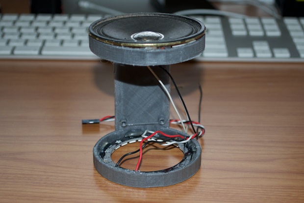
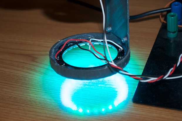
The chassis will be inserted within the main housing so that the Neopixles are about 10mm off the table. If I lift up the assembly, you can see how nice and bright it illuminates my desk.
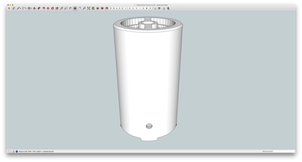
I then got to work on designing the main housing. The speaker will point upwards and have the “play” button centered on the top. This poses some design challenges, but I think I’ve come up with a design that’ll work.
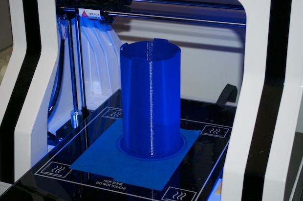
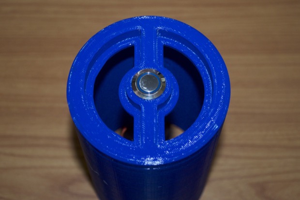
The clock is going to sit at 6” tall so that they'll be a nice air gap inside for the speaker. As a test, I printed just the top portion of the enclosure just to make sure that the speaker would fit nice and tight within the enclosure. If the speaker fits, then the inner chassis will fit too.
It’s perfect. Rather than use a perforated plastic or metal grate, the plan will be to cover the top openings with some fabric, like a traditional speaker cabinet.
The 16mm hole for the push button is perfect. I thought I’d have to slide the button in and secure it with the included nut, but the layers in the print act like threads and allow me to actually screw it in fairly tightly.
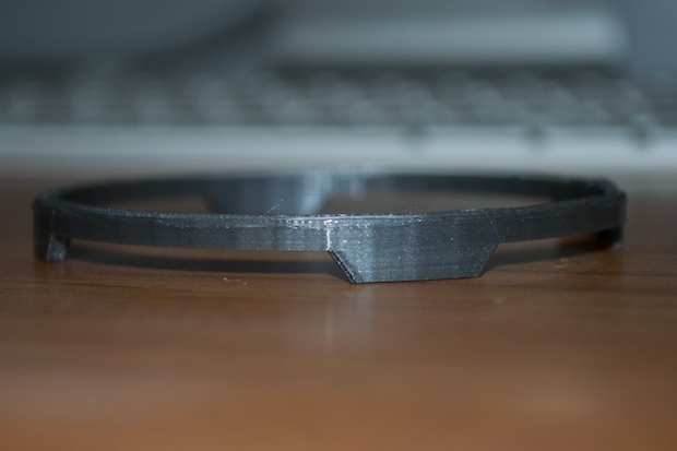
The bottom of the enclosure needs to have some feet so that the light from the Neopixels can illuminate the surface that the clock is sitting on. I made them into some cool looking trapezoids.
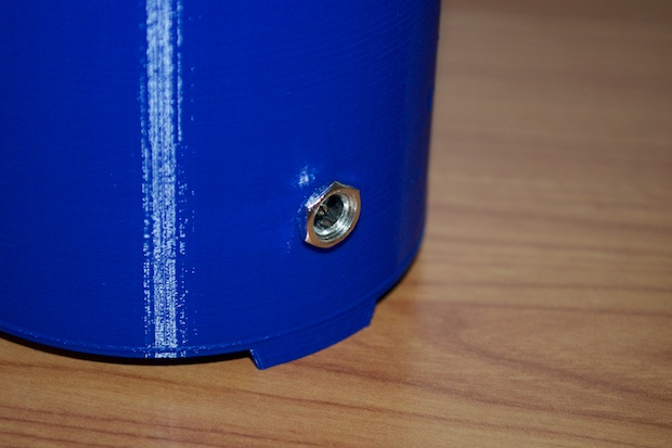
I also incorporated an 8mm hole for the DC barrel jack. The original plan was to make the clock battery powered, but if my experiments with my
Mini OLED Clock have taught me anything, it's that battery powered devices are more trouble than they're worth. It'll just be one more device in the house that I have to charge every other day. Not to mention, I’ve used up all the interrupts with the Neopixels and the VS1053 board. I couldn’t put the ATmega to sleep and wake it up if I wanted to.
With all the test prints complete and all the dimensions verified, it was time to print the completed model.
It took a little over 10 hours to print. It came out amazing. I was going to print it in black, but I think I'm going to give it a light sanding and a few coats of black paint. So it doesn't matter what color I use. I had a full roll of blue, so I thought it would be a better idea to save my black PLA for when I really need it.
Wow, that’s a perfect fit.
The chassis slides right in with a little force and is held in place with friction. There’s no way it’s falling out. I could ever put a few drops of hot glue in there if I wanted to play it safe.
The hole for the barrel jack also came out perfect. There’s just enough thread sticking out for the nut to go on nice and tight.
I really like the illuminated push button. Just like my test print, it fits perfectly.
It has a resistor built right in, so there's no need to add one to the design. (Which is a good thing since I already sent off for the PCB.) I suppose if it came down to it, I'd just solder one inline with one of the leads. Otherwise, all you have to do is connect power and your good to go. However, I thought it would be really cool to have the LED "breathe". I can imagine that anyone who comes across this clock in my house is going to just assume it's just some kind of Bluetooth speaker. So I want that LED to be somewhat inviting; begging to be pressed.
Sounds like a cool idea, but how do I PWM this LED when I just thought of it now and I already sent off for the PCB?
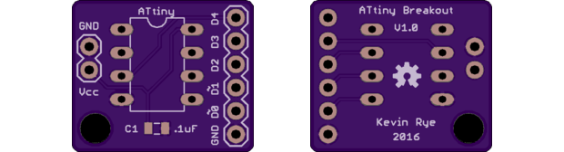
The answer is an ATtiny85. As a test, I put together a sketch to pulse the LED in the button and connected it to my ATtiny Programming Shield. It looks awesome.
All I'll have to do it put together a tiny little breakout board for the ATtiny85, connect it to the LED, and power it in parallel with the main board.
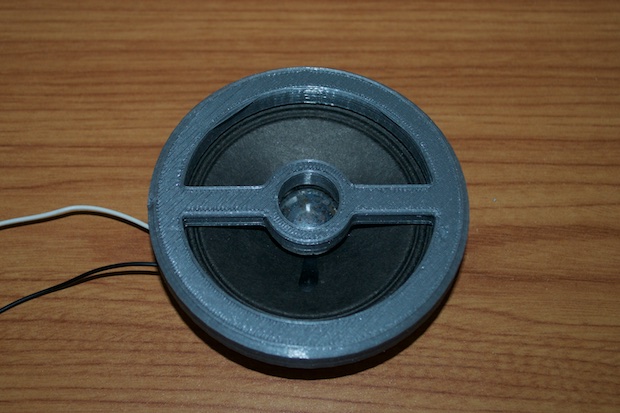
I also want to put a small button board on the bottom of the inner chassis so that I can set the time. I don’t want to mess around with putting holes in the enclosure for buttons. Once the time is set, it’s set. There’s no menu options or alarms to mess with so the buttons don’t need to be prominently displayed.
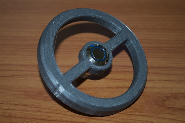
I created a small round PCB with buttons for the hours and the minutes.
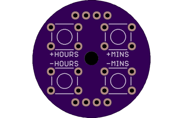
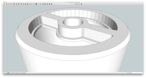
I then updated the model for the inner chassis to accommodate the new board.
I can’t wait for these PCBs to arrive!
See this project from start to finish:
Adafruit's VS1053 MP3 Player Breakout Talking Clock - Part I Talking Clock - Part II Talking Clock - Part III
Talking Clock - Part IV Talking Clock - Part V Talking Clock - Part VI