With all the clock code written and the audio stuff worked out, it was time to pay closer attention to some of the details. Like properly driving the filaments.
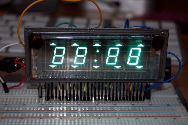
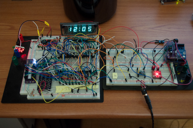
Applying a DC voltage across the filament not only causes the side of the display that's grounded to appear brighter than the other, but it can also cause ghosting along the display. Seen here, the filament is powered via DC while all the anodes are connected to 25 volts. It's obvious from the brighter digit on the right that it's the side that's grounded. Look how much brighter it is.
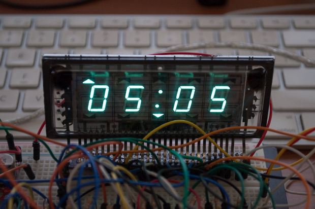
Although the filament is powered via DC, multiplexing the digits seems to mitigate this effect. Here, the anodes are multiplexed, while the filaments are still DC powered. It's not bad. It doesn't seem to be a huge problem with my clock. Or, it could also just be coincidence.
Not being one to take shortcuts, I wanted to find a way to power them via AC. This is easier said than done. I'd have to use a center-tapped transformer that would take 120V mains voltage and knock it down to 2-3 volts. That doesn't sound ideal, or practical. I thought about just configuring two pins on an ATtiny to alternate HIGH/LOW. However, the datasheet indicates that the typical current usage is 120 mA. That'll let the smoke out of the ATtiny.
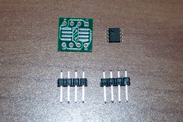
After a little searching, I think I found the perfect solution for powering the filaments of my VFD clock: the LM9022. The LM9022 is a Vacuum Fluorescent Display Filament Driver. You can't get any more of a dedicated chip than that! It's just too bad, like the displays themselves, that it's obsolete. eBay to the rescue! I found a 10-pack for $7 bucks.
In order to prototype with one of them, I'd need a SOIC-8 to DIP adapter. Again, eBay to the rescue. A 10-pack for a $1.
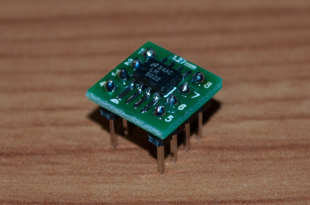
I solderd things together and I was ready to pop one onto my board for prototyping.
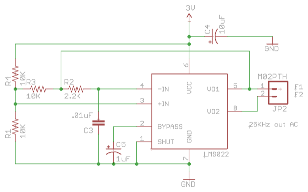
Consulting the datasheet, I put together a little schematic. Without the need for an input signal, this guy should self-oscillate and put out an AC signal on V01 and V02.
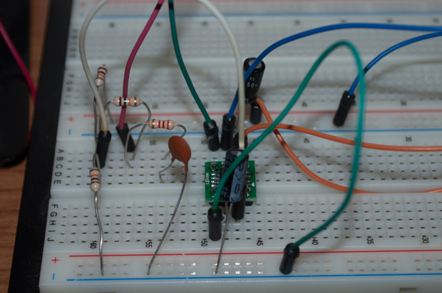
I added the components to my breadboard and connected the outputs to my oscilloscope.
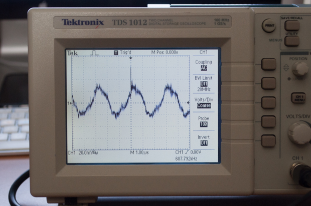
Yikes! That's ugly! That's not going to do at all. I played around with it for a few hours but ended up ditching the whole idea of driving the filaments via AC. I just couldn't get it to work. It just seems like more trouble than it's worth at this point. Maybe I'll leave this as a project for another day. For this clock, I think I'll just stick with powering it with DC; since it doesn't really seem to be a problem anyway.
I decided to just go with a 3V regulator. I have a whole bunch of these left over from my nixie clock, so might as well use them when I can.
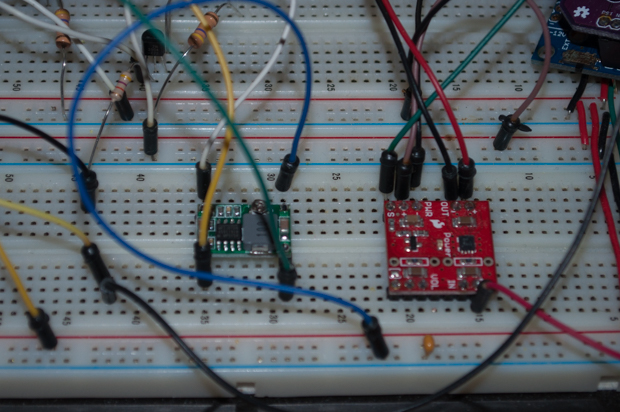
And there it is. Prototyping complete. I even swapped out the Arduino Uno with one of my Bare Bones Arduino PCBs to make sure everything runs standalone.
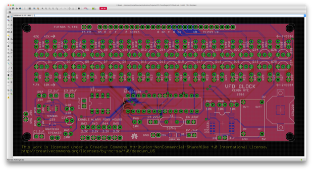
I then put together the PCB. It's pretty big. It's going to cost about $60 bucks to get three made by OSH Park. With the exception of the audio chip, I tried to go all through-hole.
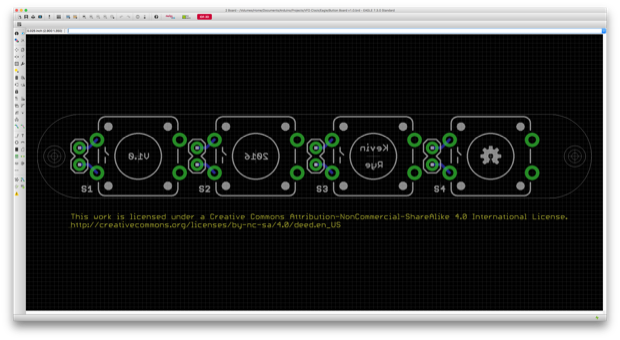
I want to put the buttons on top of this clock, instead of hiding them on the back like I usually do. However, the button board that I used on my
nixie and
LCD clocks is too small. I want to use larger buttons this time. I took the PCB for the mini button board and swapped out the buttons for larger ones.
I then exported the PCBs from Eagle so that I could put together a 3D model. This will help me later on to design a case for it.
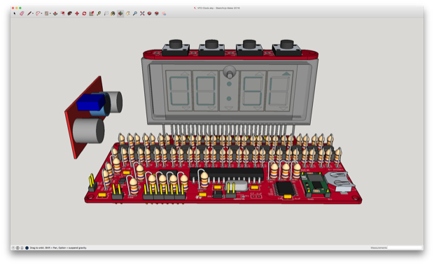
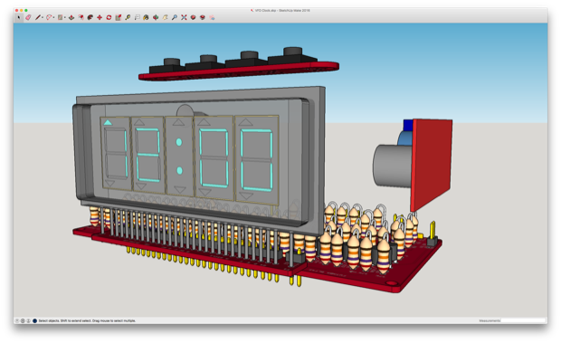
I was even able to incorporate the display into the project with the breakout board attached. This way I don't have to unsolder it. That'll probably destroy the display.
All thats's left to do now is order the PCBs, but I think I'll wait until after the holidays. I still have some Christmas shopping to do!
See this project from start to finish:
I Finally Figured Out This Vacuum Fluorescent Display VFD Clock - Part I VFD Clock - Part II VFD Clock - Part III
VFD Clock - Part IV VFD Clock - Part V VFD Clock - Part VI Clock Button Panels