While I waited for the
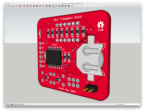
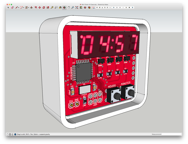
Mini 7-Segment Clock v3 PCBs to arrive, I got to work on designing an enclosure. First, I exported the PCB from EAGLE to SketchUp.
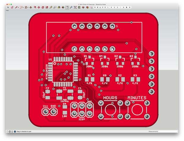
I then assembled a complete 3D model with all the necessary components.
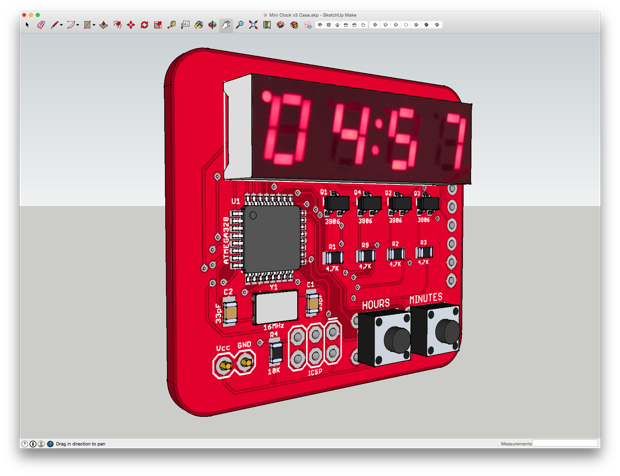
With the 3D model complete, I could then design an enclosure to house the PCB and know exactly what it's going to look like before printing it. I even incorporated a little cable strain relief.
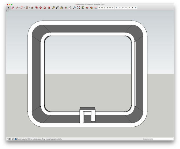
There are no mounting holes on the PCB, so I can't use board stands. I had to think of an ingenious way to secure the PCB into the enclosure, keeping both sides of the PCB visible, with a model that I can actually print
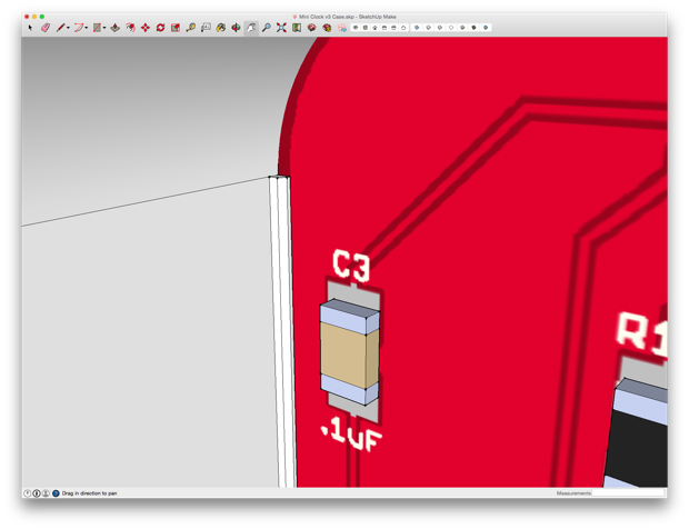
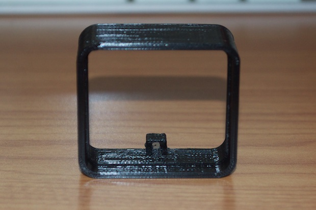
The solution was to incorporate some little raised rails along the inside of the enclosure. The PCB will be held in place by snapping it into the 3D-printed frame between the inner-divider and those rails.
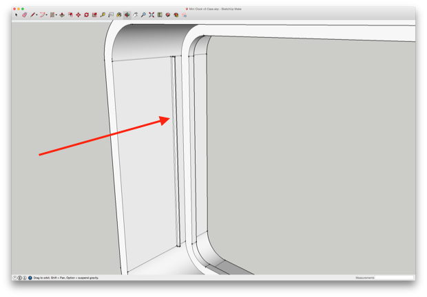
Just like so…
The design is very minimal, it's just enough to keep the clock upright. I think it's going to look pretty sweet. I don't want to hide the PCB in a little project box where all you can see is the display. I want to showcase the PCB and the electronics.
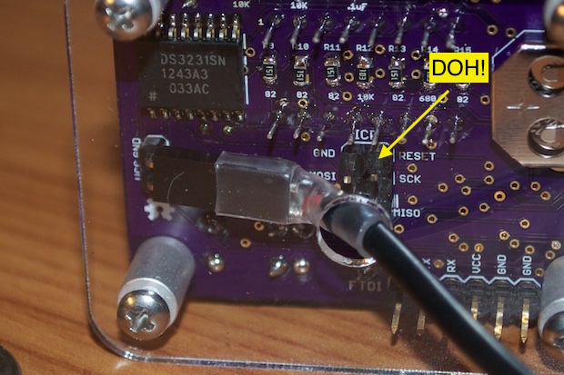
The PCB has a 6-pin ICSP header for burning the bootloader, but I'm not going to solder in a header. I've always wanted to try and program a chip with pogo pins. What's the use of soldering in a header if it's only going to be used once? Seems like a waste. Not to mention, sometimes it just gets in the way. The ICSP header on
version 2 of the Mini 7-Segment Clock got in the way of the power cord. It wasn't apparent until I screwed on the back panel and realized what little space I had to work with. I managed to squeeze the cable through the hole in the acrylic, but it was tight.
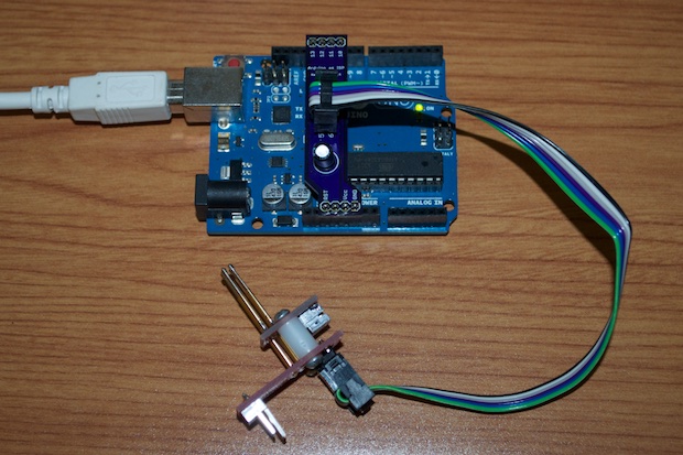
To help burn the bootloader without the use of a 6-pin header, I picked up SparkFun's
ISP Pogo Adapter for $9.95.
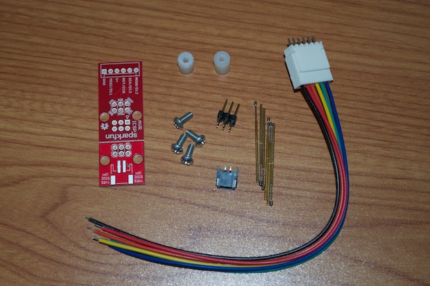
I soldered on some leads so that I could connect it directly to my Arduino.
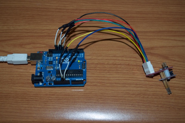
After hooking it up, I thought to myself what a pain in the butt it's going to be to connect this thing to my Arduino every time I need to burn a bootloader. It was then that I remembered that I already solved this problem.
I could just connect the pogo adapter to my
Arduino as ISP Shield. I designed and built this thing 8 months ago and I still haven't had the chance to use it. I'm not even sure if it works! Maybe now I'll finally get to validate it.
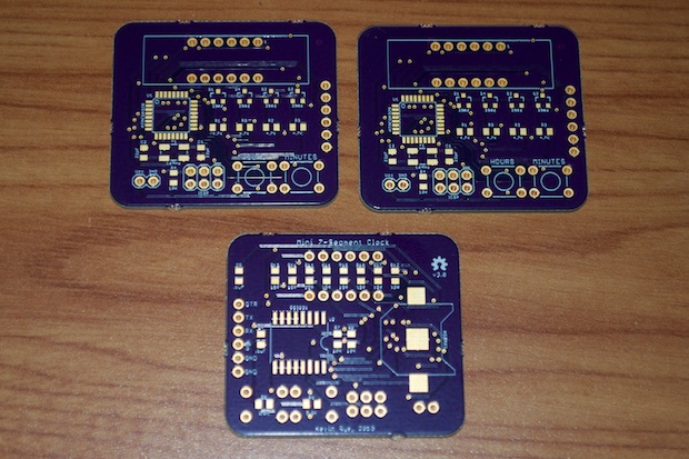
About 2 weeks later, my PCBs arrived. Build time!
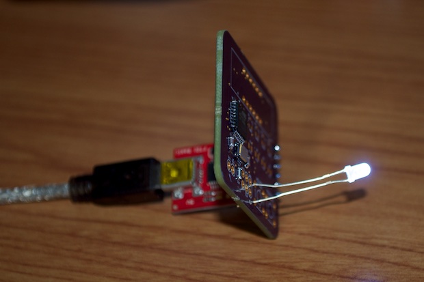
First I soldered in the ATmega, the crystal, and the supporting caps and resistors. I then burned the bootloader to the chip using the pogo pin adapter connected to my Arduino as ISP shield.
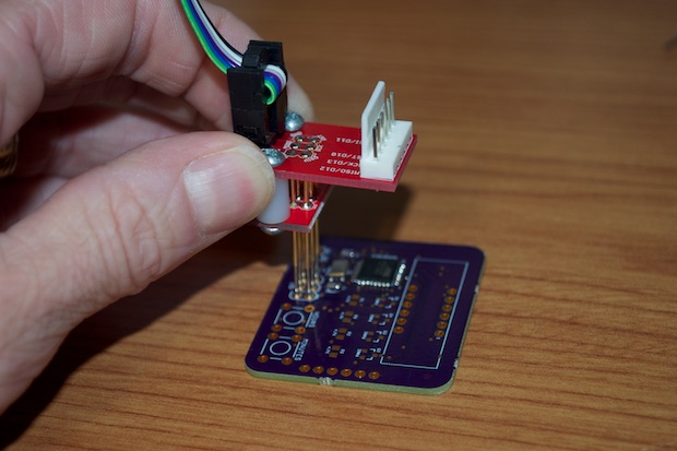
I just had to hold it in place, select "Burn Bootloader" from the Arduino IDE, and wait a few seconds. It was so easy, and it worked on the first try. I guess my Arduino as ISP shield works!
I then uploaded a blink sketch via my FTDI adapter. Again, it worked perfectly. Come to think of it, I probably didn't need to solder in the 6-pin header for that either. I probably could have just pushed a 6-pin header into the FTDI adapter and just hold it in place while it uploaded the code. Why didn't I think of that? Oh well, next time.
The easiest way to check that the sketch was running was to pop an LED into where one of the push buttons go. The push button is connected to pin A0, so I set that to blink in my sketch. Success!
I only have 2 displays, and it's very unlikely that I'll get my hands on any more of these since they've been obsolete for quite some time. I looked for them on eBay, Mouser, Digi-Key, Newark, and Jameco and came up empty handed. Since I have 3 PCBs, I figured that I'd go ahead and assemble a second clock just to use up the display. It's not like I have any plans to incorporate it into another project. I only designed this clock because I had the displays. The FTDI trick worked on the second one. I didn't have to solder in a header. I just had to hold it at an angle so that the pins on the FTDI programmer made contact.
With the clock assembled and working, it was time to print the case for it.
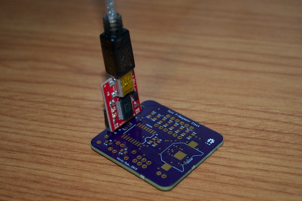
I then cut up a USB cable and soldered on a JST connector.
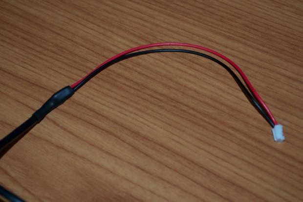
I then soldered a JST socket to the back of the PCB, connected the USB cable, and secured it within the cable strain relief.
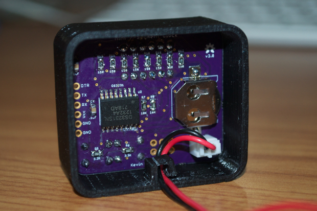
Nailed it.
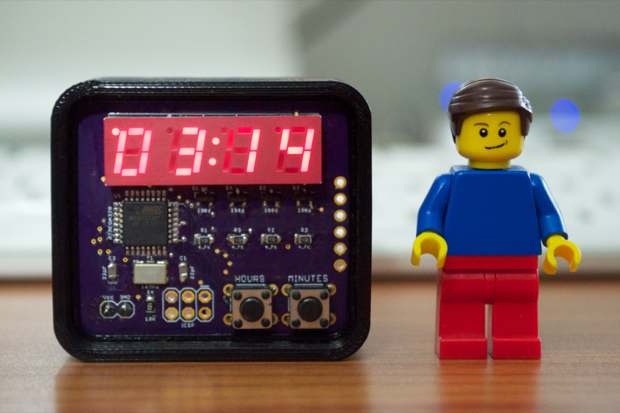
I hope the LEGO minifig gives you a good sense of scale. This clock is pretty small. It's amazing how small the Mini Clock has become after just 3 iterations. Just look at how small it is compared to version 1 and version 2.
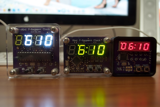
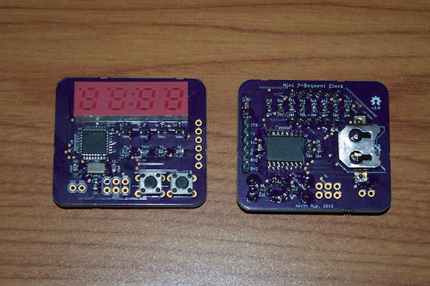
Maybe it's hard to tell once they're all buttoned up within their enclosures. Just take a look at the bare PCBs.
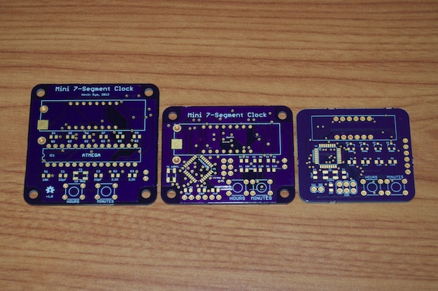
Hummmm... 2013, 2014, and 2015. I'm starting to notice a trend!
See this project from start to finish:
Mini 7-Segment Clock V3, Part I Mini 7-Segment Clock V3, Part II