I shelved the E-Paper clock for a few months so I could finish up some other stuff. (
Bare Bones Arduino,
RGB Night Light,
SpeakJet Board, and the
7490 Clock.) I had planned from the start to design the board around the
Dangerous Prototypes 80mm x 80mm Sick of Beige case.
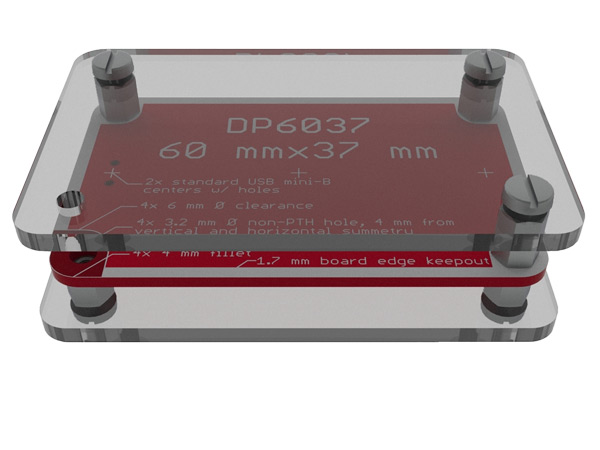
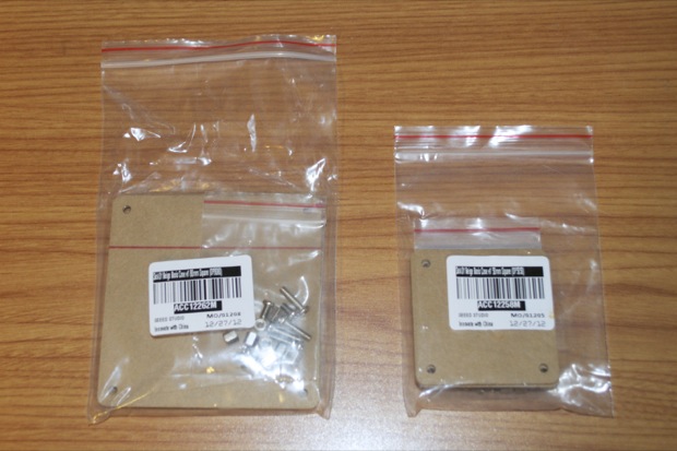
I had ordered an 80mm x 80mm case for the E-Paper clock and a 50mm x 50mm for the SpeakJet board. It took 18 days to show up. All that waiting sort of put a damper on things.
While I waited for the Sick of Beige case to show up, I went full-steam ahead with some other stuff. I crossed the point of no return on those and ended up shelving the E-Paper Clock until they were done.
Well, it’s time to switch gears back to the E-Paper clock and wrap it up.
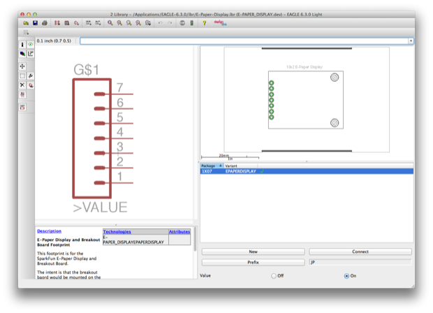
I needed to design a footprint for the
SparkFun E-Paper Breakout Board and the
E-Paper display. Ideally, I would have liked to have designed the circuit used on the breakout board right into my PCB, but there’s no way I would have been able to solder such fine-pitched connectors by hand. I just incorporated the whole breakout board in as a daughter board. Not to mention, SparkFun just recently retired the display. So I probably couldn’t order another one anyway. For the $15 I paid, I might as well just incorporate it into the clock. I’m not going to need it again.
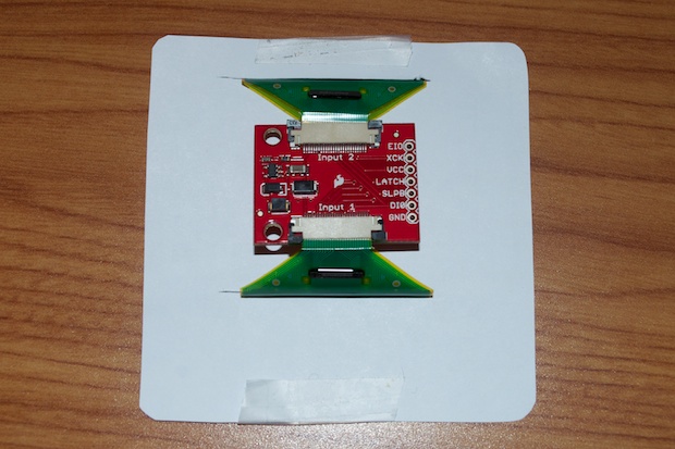
I put some slots on the board so that I’ll be able to slide the ribbon cables through to the back and connect them to the breakout board that’ll be soldered to the PCB via a 7-pin header. I also have 2 holes there for standoffs.
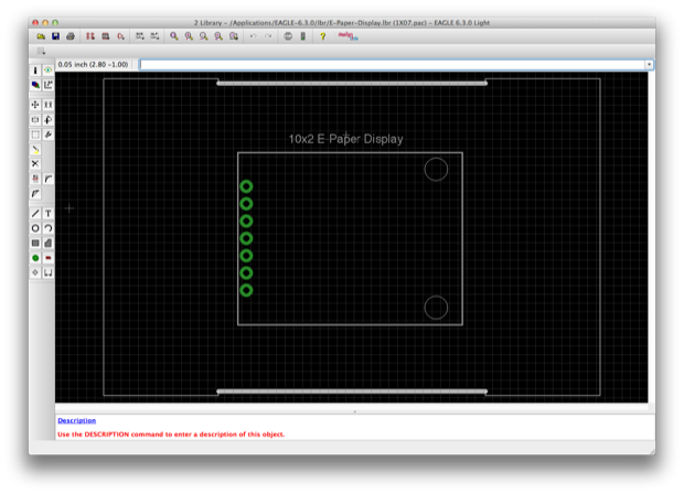
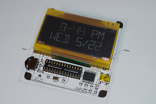
I printed it out and made sure that everything lined up correctly.
With that out of the way, it was time to chalk up a schematic and start laying out pieces. For the most part, the circuit closely matches that of my
LCD Clock. Other than the display, I haven’t added any new features.
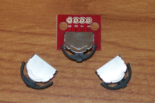
It was around that point that I shelved it to work on the other stuff that was a little further along in development. I had picked up these cool
3-way navigation switches to use on the SpeakJet board. Since the SpeakJet board was only 50mm x 50mm, I wanted to use one in favor of 3 separate buttons in order to save some board real estate. Since I had an extra one left over, I figured it would look pretty cool on the E-Paper Clock.
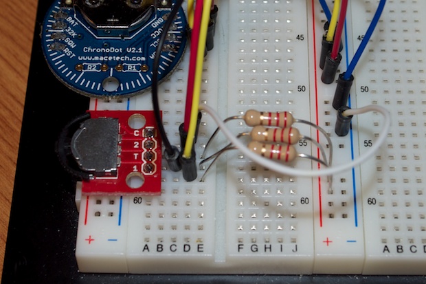
I added the 3-way nav switch to my breadboard and added a ton of code to use it in the time-setting function.
Pressing the center button brings up the settings menu, similar to the menu I used on rev 2 of the code for my LCD clock.
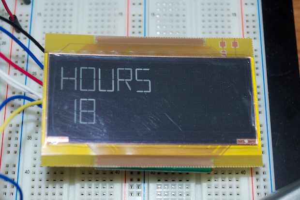
You can then press the nav switch up or down to increment/decrement the numbers. Pressing the center button again moves you to the next field….
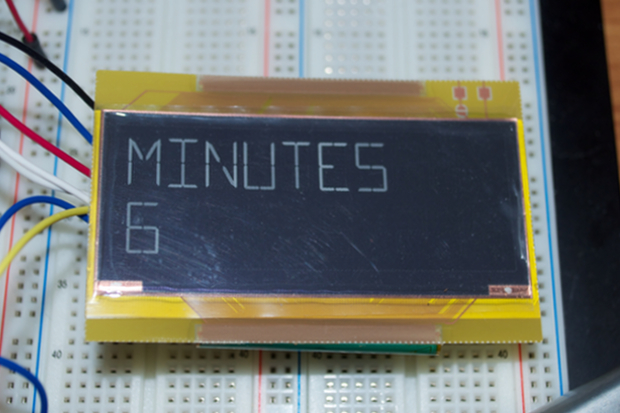
…and so on and so forth until you get back to the main display. I might need to update the timing of the display since this thing is pretty slow to update. You have to wait a second or two for the display to show you the next selection.
The great thing about e-paper is that the image is persistent. You don’t have to power the display until you plan on updating it. I thought that would make it a pretty cool choice for a low-powered battery operated clock. I’ve been wanting to play around with some low-powered battery operated stuff for a while, so this looked like a good opportunity to try my hand at incorporating a Lithium Ion rechargeable battery.
I picked up a few
1000mAh Lithium Ion batteries from SparkFun, as well as a
breakout board.
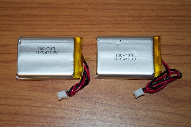
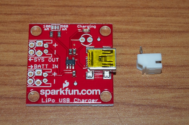
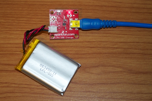
I just needed to solder on the JST connector and the batteries were on their way to being charged.
Once the batteries were fully charged, I swapped out my Arduino board for my Bare Bones Arduino board to test it running with a battery. (The less power consumption the better.)
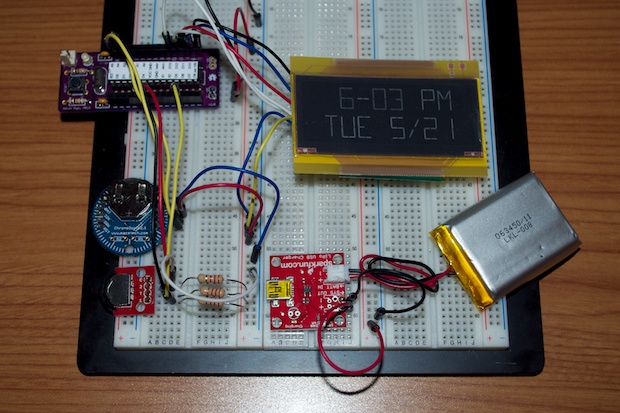
My DMM must be on the fritz. I measured the current so I could calculate my battery runtime, but the meter is only displaying 50 mA. That can’t be right, can it?
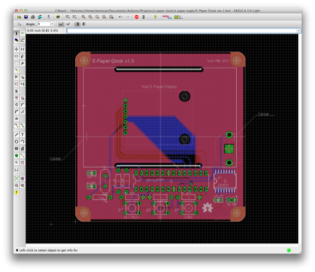
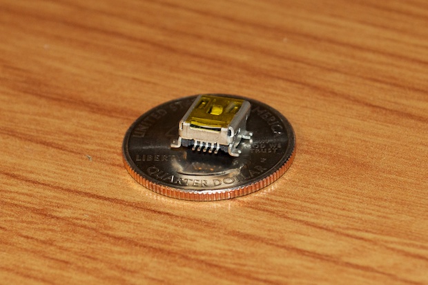
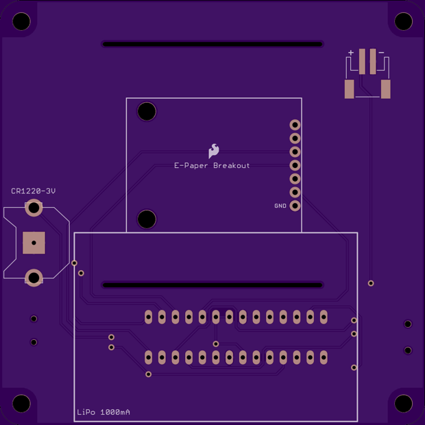
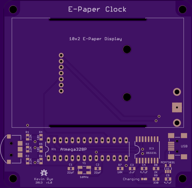
Since I started this project, I’ve made the switch over to SMD components. I updated my Eagle file to use 0805 parts for all the resistors and capacitors. I added the battery, the 3-way nav switch, and the circuitry for the battery charger. I just hope I can solder the pins on this mini USB connector. They’re tiny!
I printed out the PCB and made sure that everything looked right. I immediately noticed an error with the placement of the 3-way nav switch.
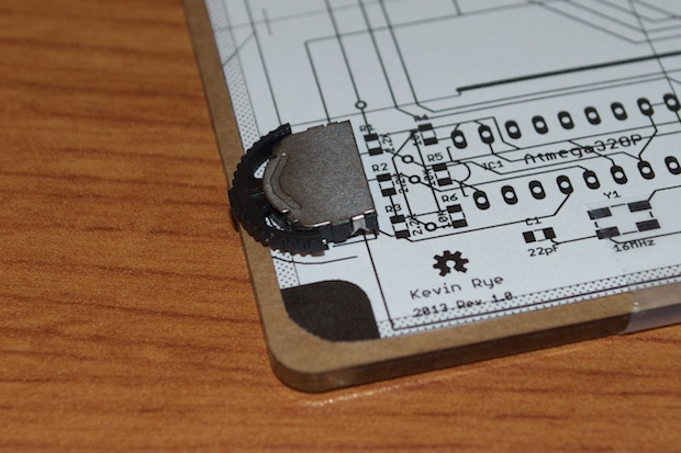
I had it hang off the board a little bit so that it would be easy to move the switch up and down, but I didn’t take into consideration the fact that the acrylic is larger than the PCB. It’ll be pretty hard to move the switch up and down with it recessed like that. To solve the problem, I just nudged the switch out a little further. There’s definitely something to be said for printing out the PCB and physically seeing how the parts play with each other.
Everything else looked good. I updated my Eagle file for some other little aesthetic things and I was good to go.
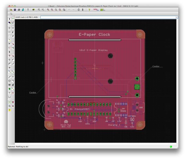
The OSH Park render looks sweeeeet!
While I wait for those boards, I can get to work on the
mini 7-segment display clock.
See this project from start to finish:
E-Paper Display E-Paper Clock Prototyping, Part I E-Paper Clock Prototyping, Part II E-Paper Clock Prototyping, Part III
E-Paper Clock Final Assembly