I was so excited when the board for this clock arrived. This is such a fun project; even if it is just for a laugh.
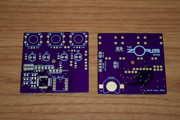
I applied some solder paste to the pads and placed all the SMD stuff before baking the board in the oven. It came out really nice. Before continuing with the LEDs, the switches, and the other hardware, I wanted to first make sure that the board worked.
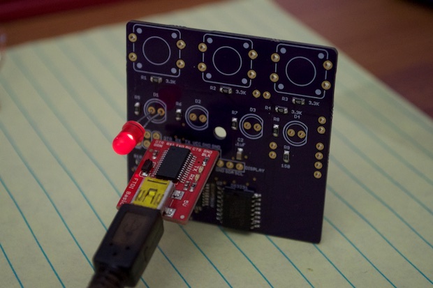
I burned the bootloader and uploaded the blink sketch. I pushed an LED into one of the holes and watched it flash. Good to go!
I then went ahead and installed all the other hardware: the LEDs, the switches, and the display. I'll have to hold off on the other stuff until the PCB is mounted within the enclosure.
For the alarm killswitch, I had the perfect thing. I don't even remember where I found this cool little switch, but I must have salvaged it from something that went in the trash. It's just two little metal contacts. When they touch each other, they close the circuit. It's perfect.
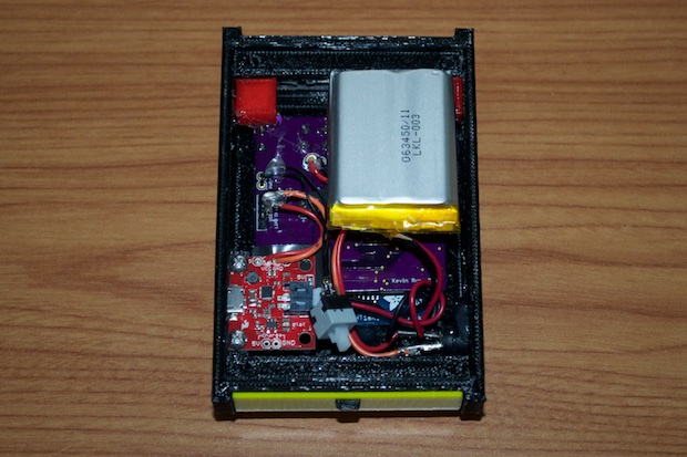
I glued it to the back of the PCB so that it was directly inline with where the killkey PCB will be inserted. Once the board slides in, it'll make contact with the switch and close the circuit.
I also installed the battery charger and the power switch, which is sort of temporary for now until I can nail down exactly where I want it to go.
Due to space, I only used one board stand to secure the PCB within the enclosure. When I pressed the set buttons, there was a little movement from the PCB. I printed out two cubes and glued them into the corners, and onto the board to stop it from moving when the buttons were pressed.
I then glued the speaker into the spot that I made for it and made the connections.
The last thing to do was connect the battery.
I put some code together to make it a clock. The buttons from left to right set the hours, the minutes, and enter alarm mode.
Once in alarm mode, the buttons from left to right set the alarm minutes, alarm seconds, and start the alarm. Once the alarm is started, the buttons are locked out. There is no way to change the alarm, or stop it. You have to use the killkey. Once the killkey has been inserted, functionally is given back to the alarm key. Pressing it again takes you out of the alarm mode and back to the clock display.
If you let the alarm run down to 00:00 the LEDs will flash and the speaker will beep. Again, the only way to stop it is to insert the killkey.
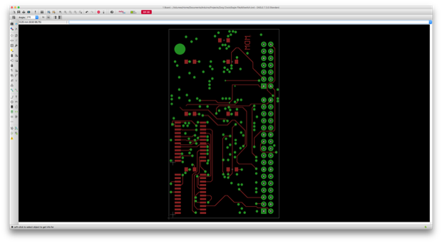
The last thing to do is design a back cover for it and make a proper killkey PCB like in the movie. Unfortunately, I ran out of black PLA, so I’ll have to wait a day or two until my new roll arrives. In the meantime, I got to work on making the PCB in EAGLE. Since this has to be a no-frills barebones PCB without a solder mask and silk, I’ll probably just make it at home with a plane copper board and some etchant solution.
 See this project from start to finish:
The “Zorg Door Bomb”…Clock - Part I The “Zorg Door Bomb”…Clock - Part II
The “Zorg Door Bomb”…Clock - Part III