I’ve been meaning to do something with these old optical drives for years. They just keep piling up. I’ve seen plenty of posts online from people making them into mini laser engravers and PCB routers, etc. It’s time to dig in and see what I can do with them.
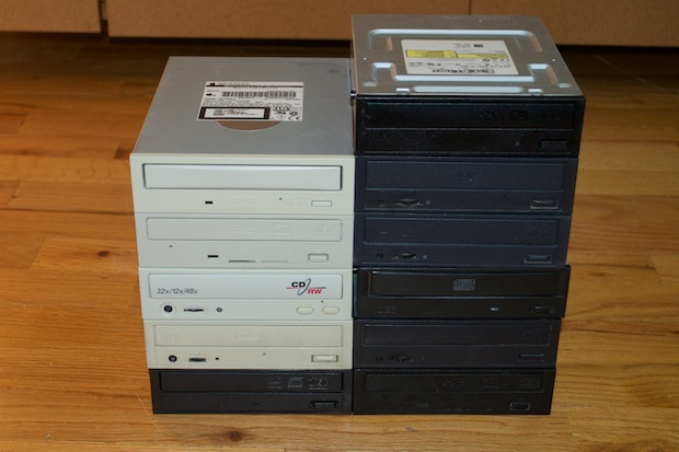
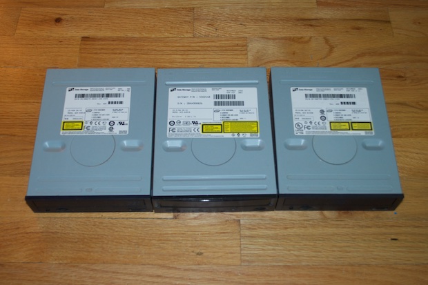
I went through the pile and managed to find three from the same manufacturer. Although one is a CD burner and the other two are DVD burners, the part numbers and dates of manufacture are so close that I’m hoping that most of the drive mechanics will be similar across all three models. If I’m going to use them for X, Y, and Z axes, it would be nice if they were all the same shape and size.
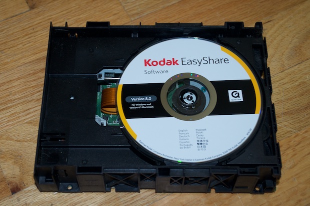
Gotta love it. Looks like this drive hasn’t been used in seven years. Why couldn’t it have been something cool like Photoshop? Then again, what would I do with a seven year old version of Photoshop?
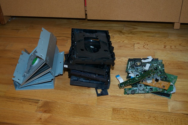
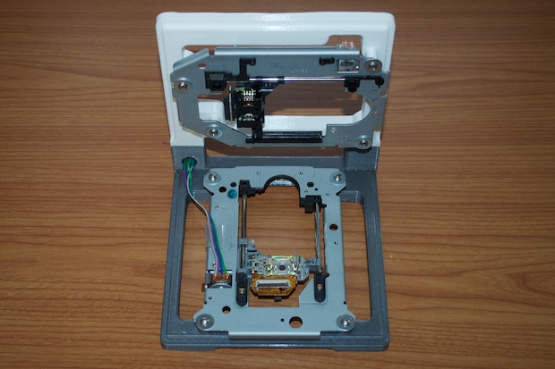
After taking all the drives apart, I sorted the junk from the keepers. Gotta recycle!
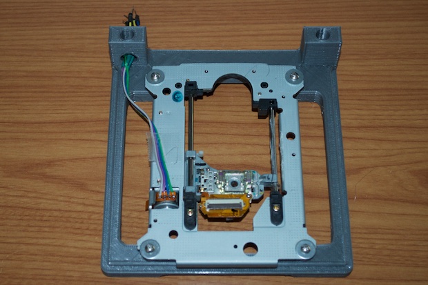
So much for my theory that they’d have components in common. It looks like with each subsequent release, the manufacture decided to reinvent the wheel. Although the top two look like a pretty good match, they use two totally different stepper motors. I actually had to crack open a fourth one because there was no way to solder wires onto the stepper motor of one of them.
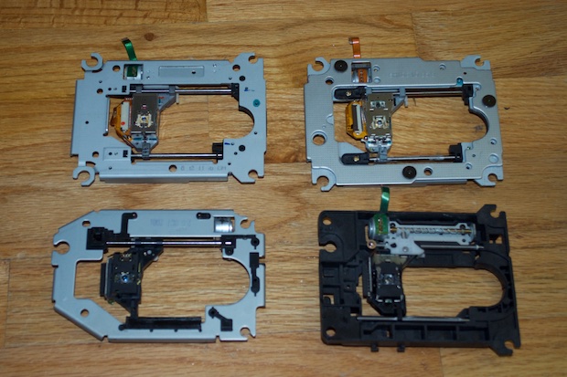
See? The solder points are way too close together. Any attempt to solder wires to them resulted in a short. I even attempted to solder directly to the ribbon cable, but that proved to be an exercise in futility.
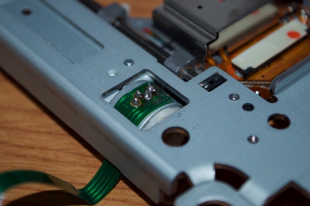
You need a stepper motor that has the solder points in a nice straight row. Much easier.

I picked up and
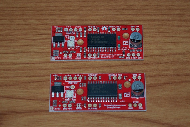
EasyDriver stepper motor driver board from SparkFun a few years ago for another project that never got off the ground. I knew for this, at minimum, I’d need at least another EasyDriver. I picked up a second board, but now I’m thinking that I should have purchased a third for the Z axis. Then again, I’m still in the proof-of-concept phase. I’m not entirely sure if I’ll even need to control the Z axis yet. It all depends on what I end up making.
I took a look at the EasyDriver tutorial on SparkFun’s site, made the connections, and uploaded some code.
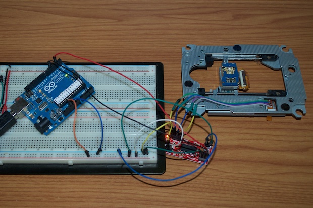
Hey! This is easy!
Proof of concept nailed. In order to start prototyping something and execute some code, as well as see what kind of space I’ll ultimately need for a PCB, I’ll need to build some sort of rig to hold the motor assemblies in an X, Y, and Z arrangement.
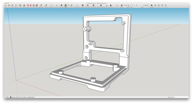
I jumped into SketchUp and got to it. For now, I’m only going to concern myself with the X and Y axes, and worry about adding a Z axis as an upgrade later on.
First thing’s first. I need to figure out the hole placement for the standoffs. I got out my trusty caliper and took some measurements. I then chalked up a minimalistic design just to test the placement.
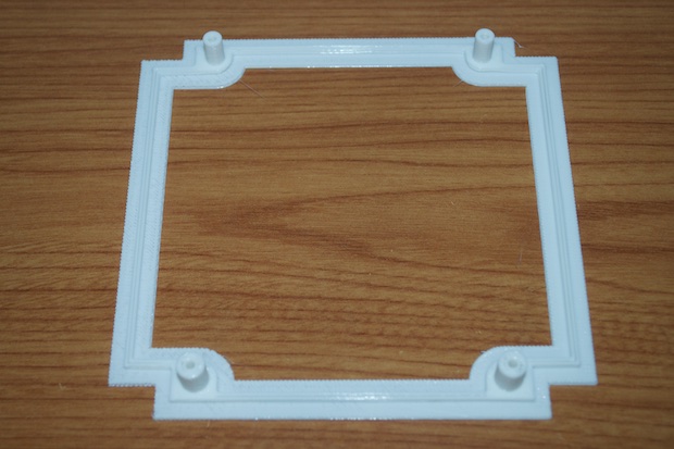
Nailed it on the first try.
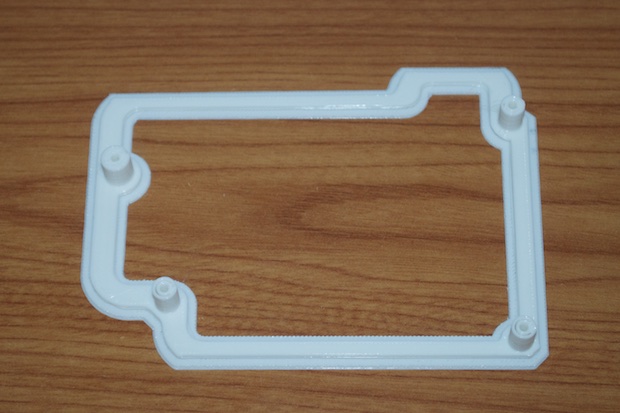
The Y-axis was a little trickier, as all the holes aren’t lined up nicely in the four corners. It took 3 prints before I got this one right.
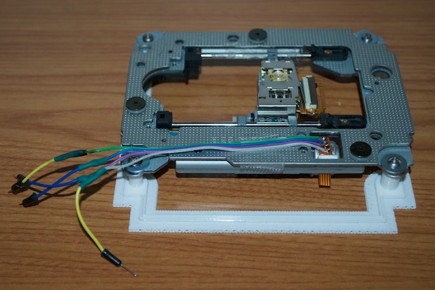
I then incorporated those pieces into my rig. The X and Y axes can be printed separately and then snapped together.
The print did come out a little crappy, but it’ll do for now. This cheap roll of gray PLA kept jamming on me.
I had a lot of trouble printing the Y-axis assembly using the gray PLA. After the third failed print, I threw in the towel and switched back to the white roll. I suspect that this won’t be the final print before all is said and done, so I’m not bothered by the mismatched colors.
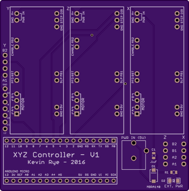
I then got to work on the PCB. It’s basically just a PCB that I can mount three EasyDrivers to along with an Arduino Micro. Normally I’d roll my own Arduino implementation, but I don’t want to have to incorporate all the USB stuff. When you can get an Arduino Micro for $25 bucks, it’s cheaper to just drop one in as a daughterboard. I even broke out a few extra pins for future expansion.
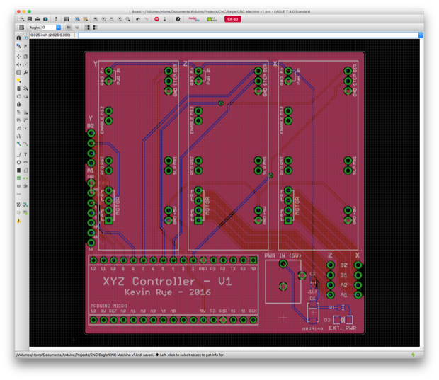
I then sent off for the PCB. I think this is as far as I can go until the PCBs arrive.
More to come…