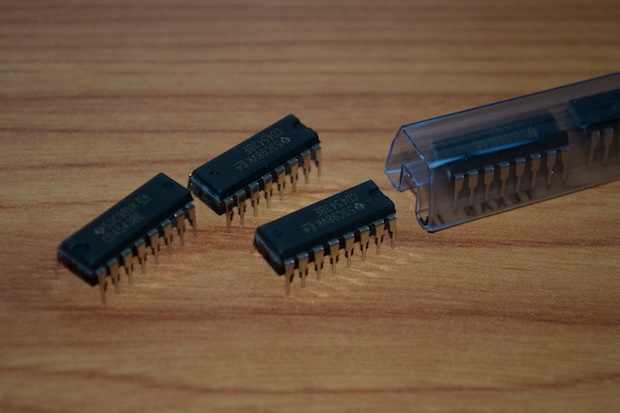
In my last post for these sweet 3" LUMEX LCDs, I left off by concluding that I'd need some dedicated LCD driver chips.
I can't believe how cheap they are. DIPs are .52 cents and SMDs are .42 cents.
Similar to some of my previous clocks, I'm going to need three sections: hours, minutes, and seconds. The minutes and seconds sections will be identical. The hours section will be a little different.
Since the hours section is the trickiest, I decided to start with that. I laid out a schematic, borrowing some elements from my
nixie clock.
I'll be using 74595 shift registers. Each shift register can address two displays.
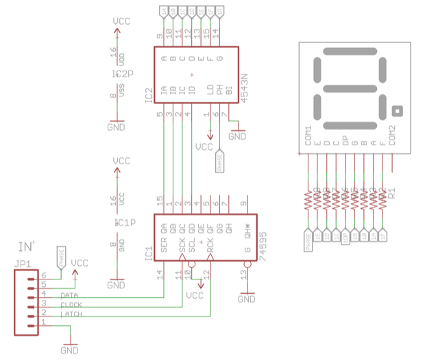
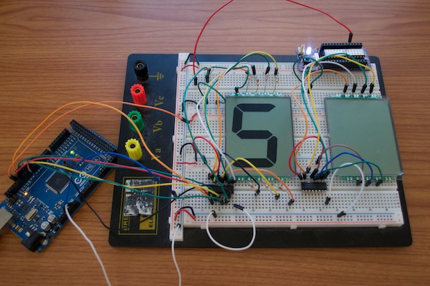
Per the CD4543 datasheet, you need to apply a square wave to the phase pin. I popped my
Bare Bones Arduino onto my breadboard (top right) and loaded the blink sketch. Instead of the default 1000ms delay between blinks, I changed it to 16ms. That results in a 60Hz square wave.
I works like a charm. The display looks perfect! I think this just might do the trick!
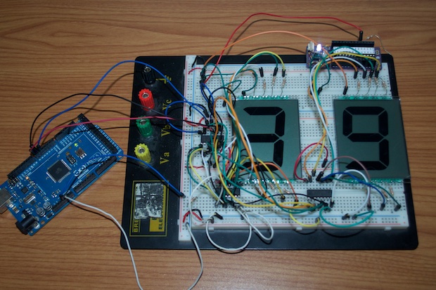
I went ahead and modified the code some more to display two digits.
I did consider using the decimal points on the LCDs as the colon separators. I was going to just flip the digit on the left upside down and hope that the two decimals points would look like a colon. However, they are too far apart and look sort of silly. So I can scratch that idea.
Unfortunately, the CD4543 only has outputs for the segments, not the decimal. Remember, these are not like LEDs where I can just attach the decimal to a digital output on the Arduino and set it HIGH to turn it on. LCDs need to have an alternating signal between the segment and the common pin.
Solution? An inverter.
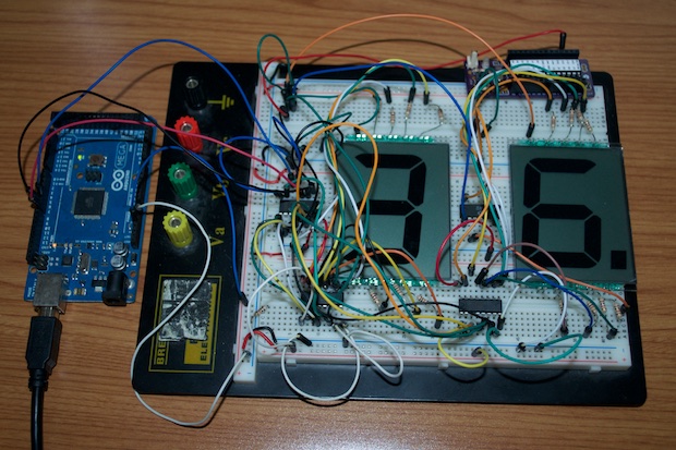
Since there is a 60Hz square wave on the phase input of the CD4543, I took that signal and passed it into a 7404 hex inverter. I then took the output of the inverter and connected it to the decimal pin. Since the output of the inverter will be out-of-phase from the signal on the common pin, the decimal will turn on.
Sweet!
One 7404 is enough to do all three sections of the clock, but I need to make each section modular. I'm not about to put a 7404 on each PCB. That would be a waste of 5 inverters. Luckily, they make single inverters. You can get a SMD package for only .38 cents.
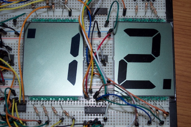
So I guess I'll just use decimals to separate the hours, minutes, and sections. It's not very "clock like", but it'll have to do. They'll always be on, so I don't need any logic in there to turn them on and off.
I then got to thinking about how I was going to implement the PM indicator. All I need to do is flip the one digit upside down, but how do I turn the decimal on and off? Since the decimal is connected to the output of an inverter, how do I stop the signal? It's the same "phase" signal that's going everywhere within the circuit. I suppose I could give it a dedicated signal, but I don't want to have multiple signals running all over the place.
Even with a dedicated signal, there is still the matter of stopping it. It's not a matter of making something go HIGH, or something go LOW. A digital HIGH or LOW on the decimal is going to cause the same display anomalies I saw before I installed the CD4543 driver chips. Not to mention, straight-up DC on a segment could potentially damage the display.
Why don't I just shut off the inverter? Instead of connecting the Vcc pin on the inverter to Vcc, why don't I connect that to a digital output on the Arduino? This way I can turn the inverter on and off at will. When it's on, an out-of-phase signal will flow, and when it's off, there will be nothing on the pin. Not high, not low. Nothing.
Hours, decimal separator, and a PM indicator. It's perfect.
Making the minutes/seconds section now will be a piece of cake.
There are some more hardware considerations to be made; like settings buttons, etc. First I need to put together a PCB so I can better visualize what everything is going to look like, how big it's going to be, and what kind of enclosure I will need. This will dictate what kind of buttons I'll use and where they'll go.
For the PCB, I first needed to create an Eagle part for the LCDs.
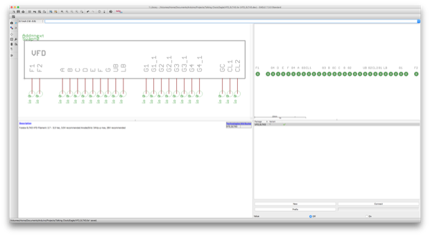
Since OSH Park gives you three boards with every order, I want to design the clock sections in a way that the one PCB will work for the hours, the minutes, and the seconds; just like I did with my
Large 7-Segment Clock.
The footprint is perfect, but that's going to be one huge PCB. Not to mention it's mostly dead space. It'll probably cost a fortune.
I uploaded it to OSH Park just to get a price. Yikes! $64 bucks! That's not happening.
Back to the drawing board.
I could just make a driver board and glue it to the back, then just solder wires directly to the pins. However, I like the idea of joining the two LCDs together as a pair and having a mounting hole in the PCB. I want to be able to do something similar to my Large 7-Segment Clock in the sense that I will 3D print some kind of frame that the three sections will mount onto.
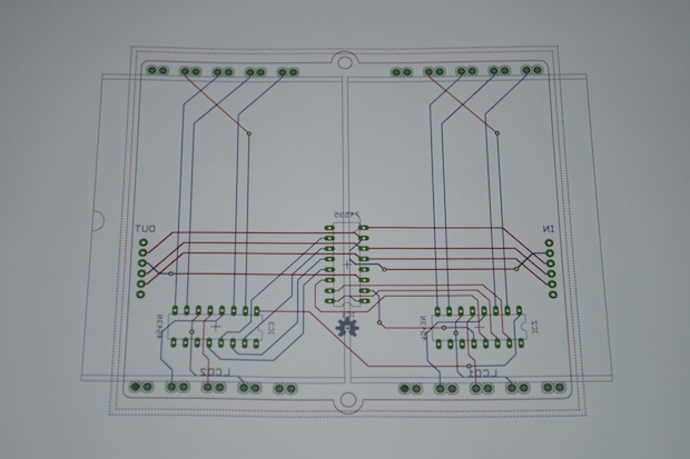
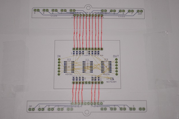
I decided to make separate PCBs for the top pins, the bottom pins, and the driver board. I will then connect the pin boards to the driver board with ribbon cables.
With that decided, I went ahead and finalized the display driver.
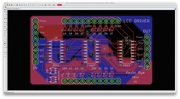
Even better, all three PCBs combined will cost less that half of one huge board.
I placed my order with OSH Park for all three boards. Here’s a render of what it should look like once it’s assembled.
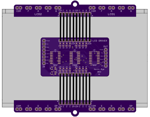
I’ll be able to better prototype the main board once these are all put together.
See this project from start to finish: LUMEX 3" 7-Segment Displays 3" LCD Clock - Part I
3" LCD Clock - Part II 3" LCD Clock - Part III 3" LCD Clock - Part IV 3" LCD Clock - Part V 3" LCD Clock - Part VI